Robot arm

A technology of a robotic arm and a rear arm, applied in the field of double robotic arm devices, can solve the problems of complex structure, inability to easily adjust down force, low overall efficiency, etc., and achieve the effects of smooth movement, improved efficiency, and simple structure

Active Publication Date: 2011-04-20
TSINGHUA UNIV +1
View PDF1 Cites 0 Cited by
  • Summary
  • Abstract
  • Description
  • Claims
  • Application Information

AI Technical Summary

Problems solved by technology

The above die pick-and-place arm structure has certain practical value and adjustment ability, but there are still some shortcomings in use: 1. Each pick-and-place mechanical arm mechanism can only install a set of vacuum suction nozzle device, and use the mechanical arm to swing back and forth to align the crystal. In this way, the working time is wasted when the mechanical arm puts down the die and returns to the pick-up position, and the overall efficiency is low; 2. It is impossible to easily adjust the downward force of the mechanical arm on the die; 3. It is impossible to easily perceive the operation on it Whether the downforce of the chip meets the operation requirements; 4. The structure is complex, the failure rate is high, and it is not in line with economic benefits
Therefore, only a set of vacuum suction nozzle device can be installed on the traditional die pick-and-place mechanical arm to swing back and forth for die pick-and-place action, and the downforce of the die being transported cannot be easily adjusted, nor can it be easily sensed by the robotic arm. Whether the down force of the transported die meets the operation requirements

Method used


Image

  • Robot arm
  • Robot arm
  • Robot arm

Examples


Embodiment Construction

[0012] Below in conjunction with accompanying drawing, the utility model feature and extremely relevant feature are further described:

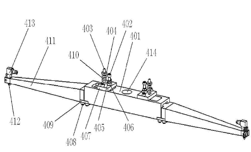
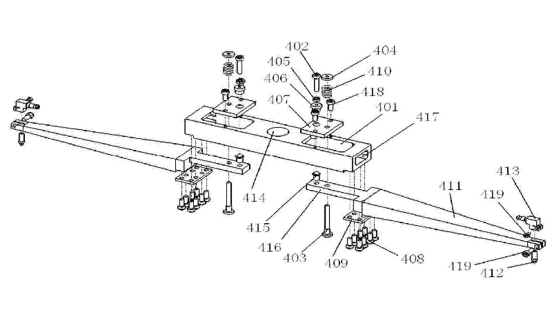
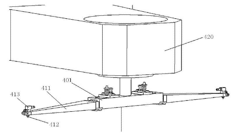
[0013] See attached Figure 1~5 As shown, the numbers in the figure are as follows: 401--rear arm, 402--rear arm electrode screw, 403--pressure adjustment rod, 404--pressure adjustment nut, 405--electrode screw nut, 406--insulation ring, 407 --support plate, 408--elastic sheet fixing screw, 409--elastic sheet, 410--spring, 411--forearm, 412--vacuum nozzle, 413--vacuum nozzle connector, 414--rear arm installation Hole, 415--forearm electrode, 416--extension of forearm rear part, 417--rear arm front end hollow, 418--support plate screw, 419--screw, 420--frame.

[0014] A kind of mechanical arm of the present invention is to install a mechanical arm mechanism on the frame 420 of the grain sorting machine or the solid crystal machine, and this kind of mechanical arm consists of a rear arm 401, a support plate 407, an insulating ring 406, and a r...


PUM


Abstract

The invention relates to a robot arm structure, in particular to a dual robot arm device which is used in a grain sorting machine or a die bonder, can simultaneously drive two sets of vacuum suction nozzle devices to carry out grain taking and placing actions and conveniently adjust the down force to the grain, and is provided with a down force sensor. The robot arm comprises a rear arm (401), a supporting plate (407), an insulating ring (406), a rear arm electrode bolt (402), an electrode bolt nut (405), a flexible sheet (409), a front arm (411), a front arm electrode (415), a pressure adjusting rod (403), a pressure adjusting nut (404), a spring (410), a vacuum suction nozzle (412) and a vacuum suction nozzle joint (413), wherein the front end of one end of the rear arm (401) is fixed with the flexible sheet (409); the front end of the flexible sheet (409) is fixed with the front arm (411); and the front end of the front arm (411) is provided with a vacuum suction nozzle fast-disassembly structure. The robot arm has the advantages of simple structure, convenient adjustment, smooth movement, and great improvement of efficiency, which meets economic benefits, and has industrial production valve.

Description

technical field [0001] The invention relates to a mechanical arm mechanism, especially a device used in a grain sorting machine or a solid crystal machine, which can simultaneously drive two sets of vacuum suction nozzle devices to carry out grain pick-and-place actions, and can conveniently adjust the loading and unloading of the grains. pressure, and a dual-arm setup with a downforce sensor. Background technique [0002] In the production process of light-emitting diode crystal grains, the whole wafer is produced first, and the wafer is divided into independent crystal grains that are completely separated from each other after dicing, and are independently adhered to the sticky blue film. In the subsequent wafer sorting process, the die sorter needs to use a vacuum nozzle device to pick up the die from the blue film and place it in the specified position; or in the subsequent die bonding process, the die bonding machine needs to use a The vacuum nozzle device picks up the...

Claims


Application Information

Patent Timeline
Patent Type & Authority Patents(China)
IPC IPC(8): B25J18/00B25J15/00B05B15/08H01L21/67B05B15/68
Inventor 董占民肖尧孙红三贾侦华孙梁伊文君田建明徐杰刘鸿飞郭金源
Owner TSINGHUA UNIV
Why Eureka
Try Eureka