

Thermal shield device for crystal pulling furnace
A technology of heat shielding and crystal pulling furnace, applied in the directions of crystal growth, single crystal growth, single crystal growth, etc., can solve problems such as heat shield damage, achieve high service life, simple heat shield structure, improve operability and safety sexual effect
- Summary
- Abstract
- Description
- Claims
- Application Information
AI Technical Summary
Problems solved by technology
Method used
Image

Examples
Embodiment 1
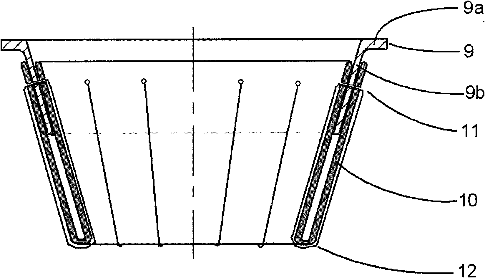
[0039] see figure 2, is a schematic diagram of a heat shielding device using a funnel structure in the method of the present invention. Heat shielding device is made up of fixing ring 9, flexible insulation material 10. The material used for the fixing ring is isostatic graphite material. The flexible insulation material adopts polyacrylonitrile-based carbon felt. Wherein the fixed ring is composed of a transverse ring 9a and a longitudinal ring 9b. The longitudinal ring is funnel-shaped, so the flexible insulating material wrapped on the longitudinal ring is also processed into a funnel shape. The flexible thermal insulation material is divided into inner and outer layers, which are respectively wrapped on the inner surface and outer surface of the longitudinal ring. The height of the longitudinal ring is 120mm, the diameter of the upper opening is 380mm, and the distance between the lower opening of the flexible thermal insulation material and the lower opening of the f...
Embodiment 2
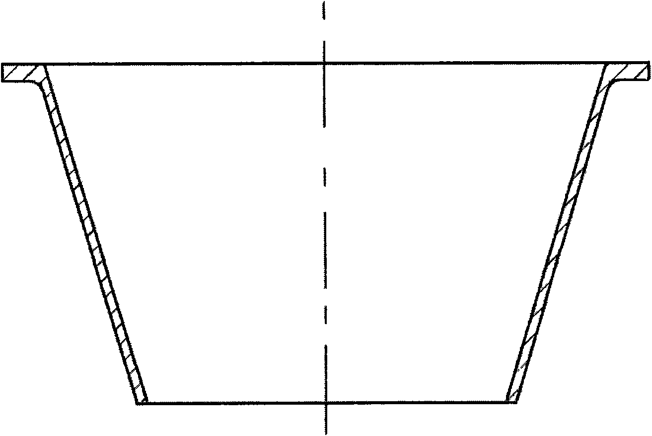
[0045] The manufacturing method of the heat shield in Example 1 is adopted, except that the longitudinal ring of the fixing ring is barrel-shaped. The inner diameter of the bucket is 380mm, the height of the longitudinal ring is 120mm, and the distance between the lower opening of the flexible insulation material and the lower opening of the fixed ring is 160mm. The height of the entire heat shield is 280mm. Fixed way like Figure 4 shown
[0046] The test method in Example 1 was used to carry out 10 times of silicon sticking tests on the above-mentioned heat shield. After cooling, it was found that the lower opening of the heat shield was deformed twice, and the geometric shape of the heat shield was not changed in 8 times. The above 10 tests did not produce cracks or damage the heat shield structure.
Embodiment 3
[0048] Adopt the method for making the heat shield in Example 1, the difference is that the longitudinal ring of the fixed ring is made of 10 slats 13 of carbon-carbon composite material whose size is 125mm (long) * 20mm (wide) * 8mm (thick). It is installed in the form of a fence, and the horizontal ring is a ring made of carbon-carbon composite materials, such as Figure 5 shown. Each slat is installed at a certain inclination angle, forming a funnel shape with a cone angle of 32°. The upper ends of the slats are connected to the transverse ring by bolts 14 . Each slat central opening diameter is the installation hole 11 of 5mm. Through the installation hole 11 on the slat, the flexible thermal insulation material is fixed on the slat with a carbon rope with a diameter of 3mm. The distance between the lower opening of the flexible thermal insulation material and the lower opening of the fixing ring is 160mm. The height of the entire heat shield is 280mm.
[0049] The te...
PUM
 Abstract
Description
Claims
Application Information