
Broken yarn detecting circuit for yarn feeder

A yarn break detection and yarn feeder technology, which is applied in textiles, papermaking, knitting, etc., can solve the problems of affecting normal work, not designing isolation circuits, and increasing costs, so as to ensure work reliability, avoid poor contact, and prevent errors. downtime effect

Active Publication Date: 2010-03-10
CIXI SUN TEXTILE SCI & TECH
View PDF7 Cites 5 Cited by
  • Summary
  • Abstract
  • Description
  • Claims
  • Application Information

AI Technical Summary

Problems solved by technology

This direct contact detection method has a disadvantage: due to the light weight of the metal probe rod itself, the swing range of the contact part of the probe rod is generally not large when the yarn is broken, and only a slight vibration occurs between the contact part of the metal probe rod and the metal sheet. contact, which leads to a large and unstable contact point resistance. After a period of use, under the action of current, the contact part of the metal probe rod and the metal sheet is prone to chemical and physical changes such as oxidation and carbonization, making this part The contact resistance of the contact resistance increases rapidly (even infinitely large), and finally when the yarn breakage occurs, the detection circuit cannot normally output the yarn breakage fault signal due to poor contact.
However, the detection device in the above-mentioned patent usually includes the cooperation of a transmitter, a receiver and a controller, the detection circuit involves many components, and the corresponding control circuit is relatively complicated, which increases the cost of design, manufacture and maintenance; and , no isolation circuit is designed in the above patent. In the case of no yarn breakage, once there is an external interference signal input, the detection circuit will send a signal to the host, which will cause false shutdown and affect normal work.

Method used


Image

  • Broken yarn detecting circuit for yarn feeder
  • Broken yarn detecting circuit for yarn feeder
  • Broken yarn detecting circuit for yarn feeder

Examples


Embodiment 1

[0037] Embodiment one, such as Figure 5 Shown:

[0038] The slot-type first optocoupler IC1 whose model is ITR8105 is connected in series as the non-contact inductive switch of the present invention in the adopting circuit A. The sampling circuit A takes the first optocoupler IC1 as the core and also includes a first resistor R1, a second Resistor R2;

[0039] Isolation circuit B includes a slot-type second optocoupler IC2 with a model number of P521;

[0040] The signal driving circuit C includes a third resistor R3, a fourth resistor R4, a fifth resistor R5, a first triode Q1, a first capacitor C1 (delay function) and a first light emitting diode D1;

[0041] The front broken yarn detection circuit includes a second rectifier bridge T2 of the same type as MB6F1A, a front broken yarn switch K, a thirteenth resistor R13 and a second light emitting diode D2.

[0042] Wherein, the anode of the light-emitting diode of the first optocoupler IC1 is connected to the anode of the...

Embodiment 2

[0050] Embodiment two, such as Figure 6 Shown:

[0051] The component composition of the circuit of this embodiment is the same as that of the first embodiment, the only difference is that the connection mode of the output end of the first optocoupler IC1 and the input end of the second optocoupler IC2 is different.

[0052] In this embodiment, the anode of the light-emitting diode of the first optocoupler IC1 is connected to the anode VCC of the 12V DC power supply through the first resistor R1, and the cathode of the light-emitting diode of the first optocoupler IC1 serves as the first output terminal ao1 and the first The second AC input terminal AC2 of the rectifier bridge T1 is connected, and the triode emitter of the first optocoupler IC1 is connected to the second AC input terminal AC2 of the first rectifier bridge T1;

[0053] The anode of the light-emitting diode of the second optocoupler IC2 is connected to the anode of the DC power supply VCC through the second re...

Embodiment 3

[0058] Embodiment three, such as Figure 7 Shown:

[0059] The slot-type first optocoupler IC1 of the model ITR8105 is connected in series as the non-contact inductive switch of the present invention in the adopting circuit A. The sampling circuit A takes the first optocoupler IC1 as the core and also includes a sixth resistor R6, The seventh resistor R7, the eighth resistor R8 and the second NPN transistor Q2;

[0060] Isolation circuit B includes a slot-type second optocoupler IC2 with a model number of P521;

[0061] The signal drive circuit C includes a ninth resistor R9, a tenth resistor R10, an eleventh resistor R11, a twelfth resistor R12, a first light emitting diode D1, an NPN type third triode Q3 and a second capacitor C2 (time delay effect);

[0062] The front broken yarn detection circuit includes a second rectifier bridge T2 of the same type as MB6F1A, a front broken yarn switch K, a thirteenth resistor R13 and a second light emitting diode D2.

[0063] Wherei...


PUM


Abstract

The invention discloses a broken yarn detecting circuit for a yarn feeder, wherein the yarn feeder comprises a front broken yarn detector and a rear broken yarn detector. The rear broken yarn detectorcomprises a rear broken yarn detecting circuit and a non-contact inductive switch which is connected in series in the rear broken yarn detecting circuit and is used for sensing the change of the working condition of the yarn. The broken yarn detecting circuit is characterized in that the rear broken yarn detecting circuit comprises a first rectifier bridge, a sampling circuit, an isolating circuit and a signal driving circuit, wherein, the sampling circuit is for collecting a broken yarn signal and is connected with the non-contact inductive switch in series, the isolating circuit is used forisolating an interference signal and the signal driving circuit is used for feeding back the broken yarn signal to the yarn feeder host. Compared with the prior art, the non-contact inductive switchis installed on the broken yarn detector in the invention, and the defect of the poor contact of a traditional touch switch after a long-time use is avoided. In addition, the isolating circuit is increased, thereby implementing the secondary isolation to the interference signal and ensuring the working reliability of the broken yarn detector.

Description

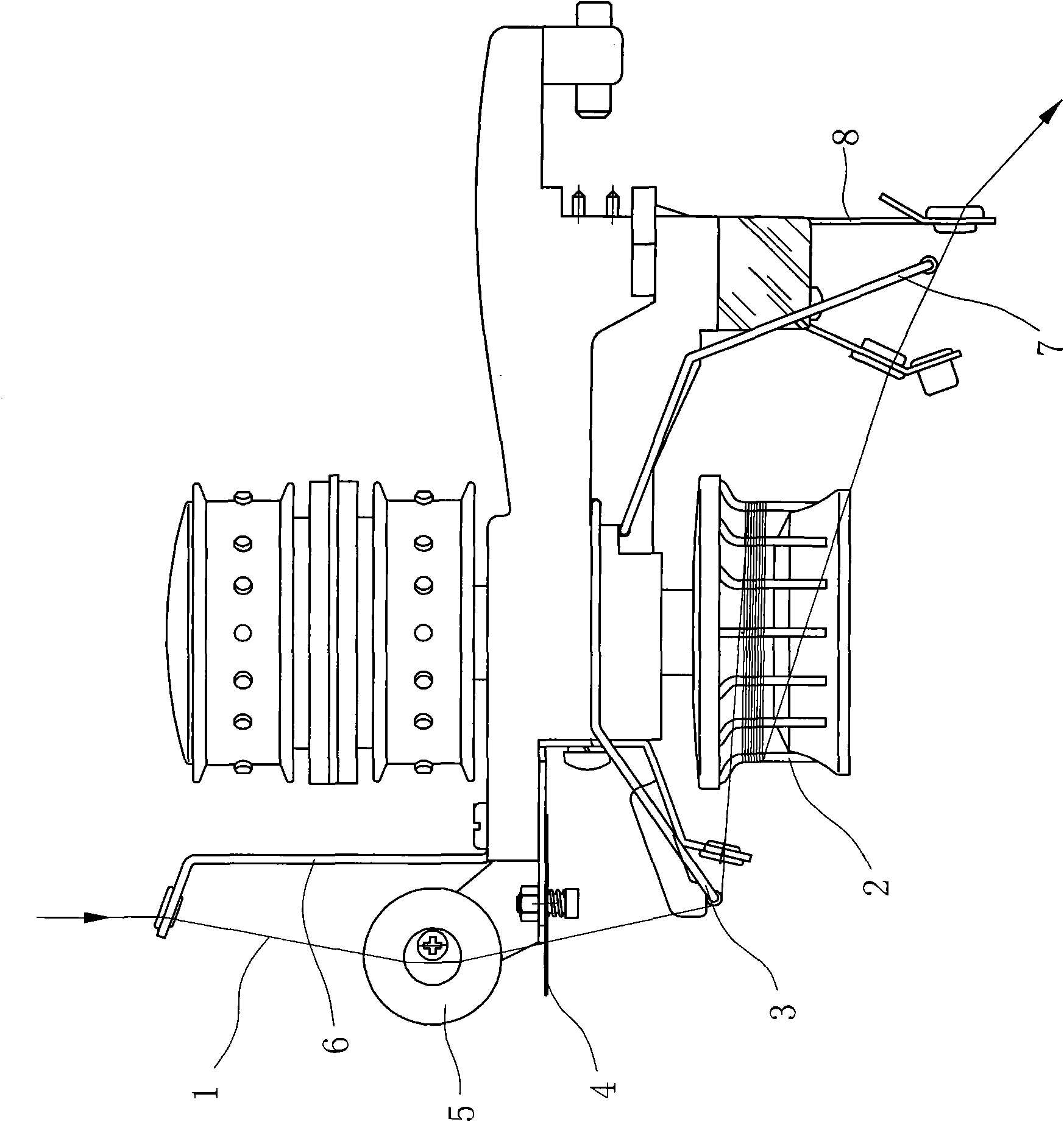
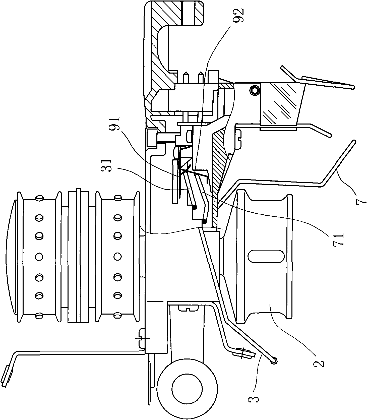
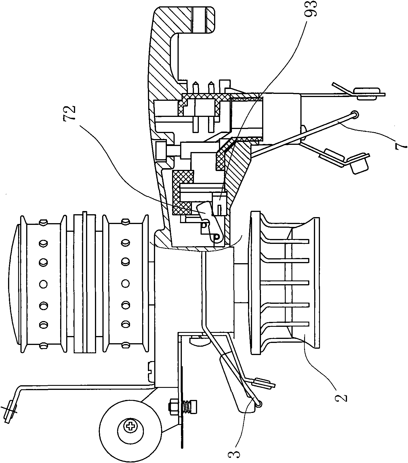
technical field [0001] The invention relates to a detection circuit, in particular to a detection circuit for yarn breakage of a yarn feeder applied to a knitting machine. Background technique [0002] The yarn feeding device (also known as the yarn feeding device) of the knitting machine is generally equipped with a yarn breakage detection device. Once the yarn breakage is detected, the main engine can be stopped in time to prevent holes and broken needles in the woven fabric due to yarn breakage. Or defects such as yarn skipping. [0003] Such as figure 1 , figure 2 As shown, it is a traditional yarn feeding device and its adopted yarn breakage detection method. Metal probe rods (generally stainless steel wires) and metal sheets (generally copper sheets) are arranged in the yarn feeder. The metal probe rods usually include There is a front detection rod 3 and a rear detection rod 7, and the contact part 31 of the front detection rod 3 and the contact part 71 of the rea...

Claims


Application Information

Patent Timeline
IPC IPC(8): D04B35/14
Inventor 高山
Owner CIXI SUN TEXTILE SCI & TECH
Learn More