Driller support device

A technology for supporting devices and drilling rigs, which is applied in the directions of supporting devices, drilling equipment, earthwork drilling, etc., to achieve the effects of reducing the size of modular structural parts, reducing the difficulty of disassembly, and reducing processing costs

Inactive Publication Date: 2010-03-10
BEIJING SANY HEAVY MASCH CO LTD
View PDF8 Cites 7 Cited by
  • Summary
  • Abstract
  • Description
  • Claims
  • Application Information

AI Technical Summary

Problems solved by technology

[0005] Aiming at this problem in the prior art, the present invention proposes to design the supporting device of the drilling rig into a modular structure, thereby solving the problem in the prior art

Method used


Image

  • Driller support device
  • Driller support device
  • Driller support device

Examples


Embodiment Construction

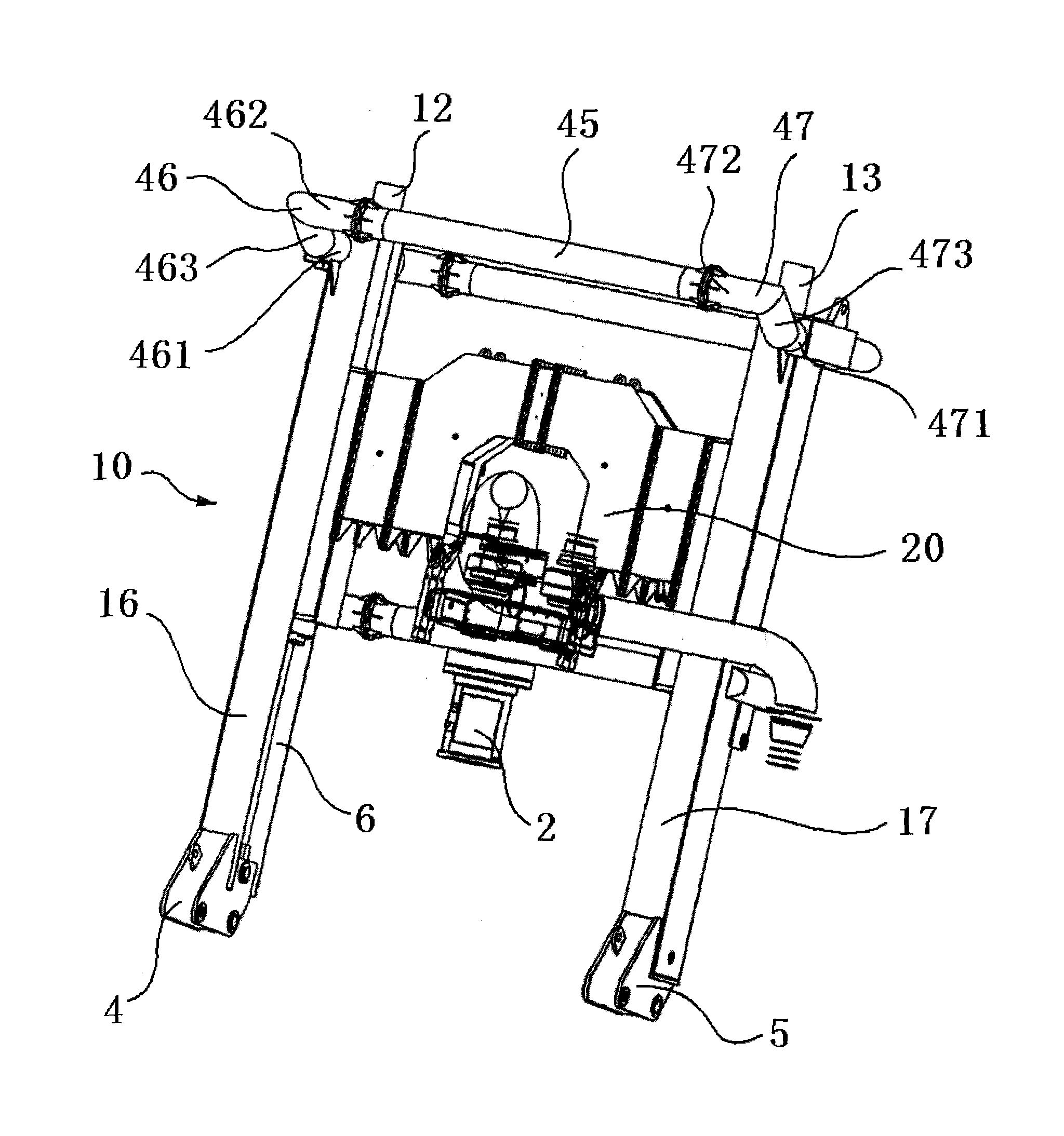
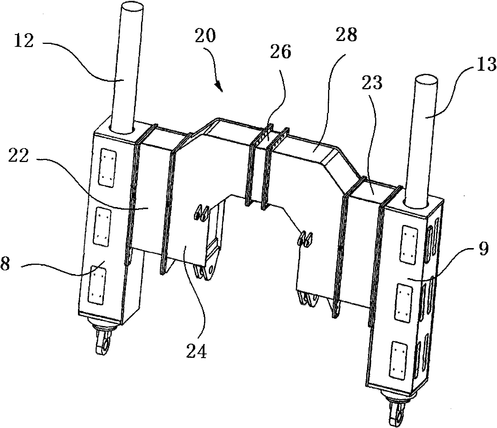
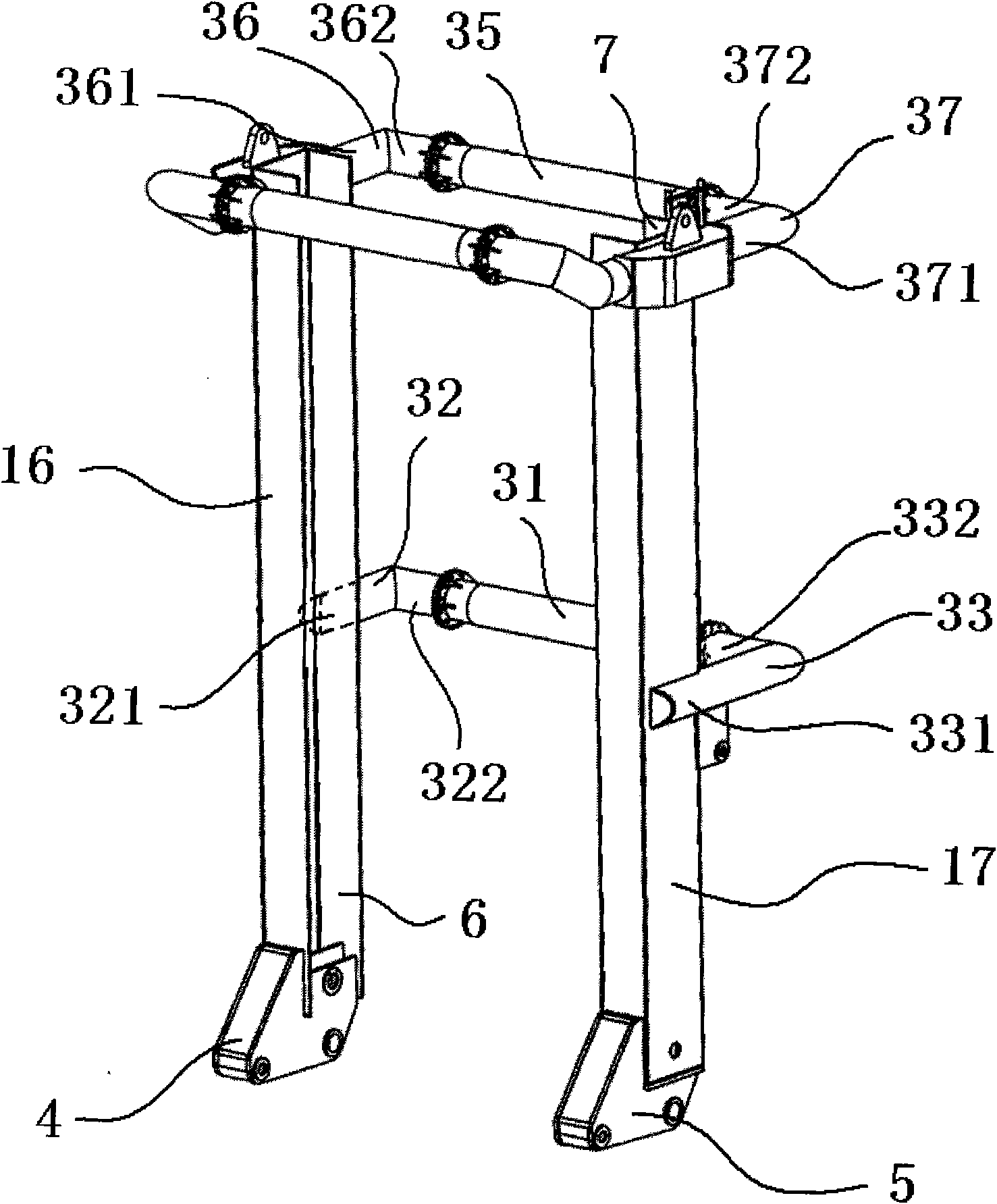
[0022] as attached Figure 1~3 As shown, in the embodiment of the drilling rig supporting device 10 provided by the present invention, the power head 2 is detachably installed on the carriage 20 . The carriage 20 can move up and down along the left mast 16 and the right mast 17 . Be provided with left chute 6 in left mast 16, be provided with right chute 7 in right mast 17, be provided with left slide cylinder 12 near left chute 6, be provided with right slide cylinder 13 near right chute 7.

[0023] In the embodiment provided by the present invention, such as figure 1 As shown, the left chute 6 in the left mast 16 has a U-shaped cross section, and the left slide cylinder 12 is located in the recessed part of the left chute 6 with a U-shaped cross section, and the right chute 7 in the right mast 17 has a U-shaped cross-section, the right slide cylinder 13 is located in the concave part of the right chute 7 with U-shaped cross-section. One end of the left mast 16 and the ext...


PUM


Abstract

The invention discloses a driller support device (10). A slide frame (20) can move along a left mast (16) and a right mast (17), and a power head (2) is detachably installed on the slide frame (20). The slide frame (20) comprises a saddle-shaped frame first support pin (24) and a saddle-shaped frame second support pin (28) which are detachably connected. The saddle-shaped frame first support pin (24) with an L-shaped outline is symmetric with the saddle-shaped frame second support pin (28) with an L-shaped outline, and a detachable middle connecting piece (26) is installed between the saddle-shaped frame first support pin (24) and the saddle-shaped frame second support pin (28). A detachable left connecting box (22) is arranged between the saddle-shaped frame first support pin (24) and a left slide box (8), and a detachable right connecting box (23) is arranged between the saddle-shaped frame second support pin (28) and a right slide box (9). The invention can be suitable for the change of drilling hole diameter by changing the connecting box and the transverse connecting piece of the masts in the slide frame.

Description

technical field [0001] The invention relates to a drilling rig supporting device, in particular to a mast structure of a reverse circulation drilling rig. Background technique [0002] In the known drilling construction technology, for example, in the large-diameter drilling construction of the foundation of high-rise buildings, and in the pile hole construction operations in various foundation works on the river bed and the submarine continental shelf, the pipe end gas lift reverse circulation Drilling rigs are being used more and more frequently. [0003] The main structural components of pipe end gas lift reverse circulation drilling rig include: working platform, gripper, power head, mast, etc. Among them, the main function of the mast is to suspend the power head, drive the drill pipe to move up and down and provide drilling pressure. [0004] Usually the drilling diameter of the drilling rig ranges from 1.5 to 4 meters and other specifications. Every time the diamet...

Claims


Application Information

Patent Timeline
Patent Type & Authority Applications(China)
IPC IPC(8): E21B15/00
Inventor 黎中银史春祥秦爱国李广伟
Owner BEIJING SANY HEAVY MASCH CO LTD
Why Eureka
Try Eureka