Engine braking device

An engine braking and engine technology, applied in engine control, engine components, machines/engines, etc., can solve the problems of complex compression braking structure, high cost, large braking power, etc., and achieve simple structure, low cost, and rigidity. Good results

Inactive Publication Date: 2010-03-17
CHINA FIRST AUTOMOBILE
View PDF0 Cites 18 Cited by
  • Summary
  • Abstract
  • Description
  • Claims
  • Application Information

AI Technical Summary

Problems solved by technology

[0002] At present, the engine braking applied on the engine is mainly divided into two types: vent braking and compression braking: vent braking has a simple s

Method used


Image

  • Engine braking device
  • Engine braking device

Examples


Embodiment

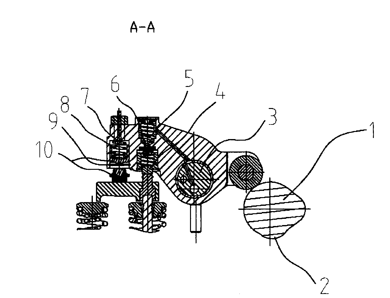
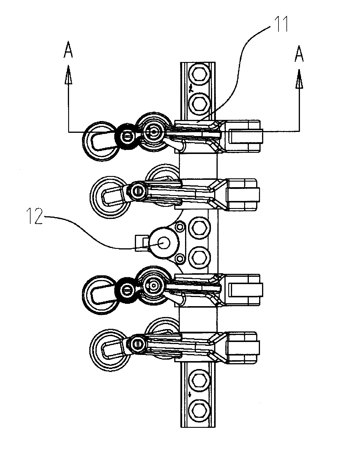
[0013] There is a brake cam 2 specially used for engine braking on the exhaust cam 1 of the camshaft. When the engine brake is required, the brake cam 2 can stop on the piston through the oil circuit control of the solenoid valve 12. Open an exhaust valve near the point to release the high-pressure gas in the cylinder to realize engine braking; when the engine does not need engine braking, the lift generated by the brake cam 2 can be compensated by the clearance in the exhaust rocker arm 11 The device compensates out without opening the exhaust valve.

[0014] There is a cavity under the hole of the adjustment bolt at the front end of the exhaust rocker arm 11 - the exhaust valve rocker arm 7, and the exhaust valve leg assembly 10 is fixed in the cavity by a snap ring, and the exhaust valve leg assembly 10 can be The cavity slides up and down, and a return spring is installed in it, so that the exhaust valve elephant foot assembly 10 is in contact with the snap ring 9 at the b...


PUM


Abstract

The invention relates to an engine braking device, which is characterized in that an exhaust cam of an engine is provided with a brake cam; two devices are integrated in an exhaust rocker; one of thetwo devices is a compensation gap device which mainly comprises an adjusting bolt-exhaust valve rocker, an exhaust valve elephant-foot assembly, a snap ring and a return spring, a cavity is formed below an adjusting bolt hole-exhaust valve rocker at the front end of the exhaust valve rocker, the exhaust valve elephant-foot assembly is fixed in the cavity through the snap ring, and a certain gap isreserved on a base plane of the cavity provided with the return spring, the adjusting bolt-exhaust valve rocker and the elephant-foot assembly; and the other one of the two devices is an engine brakeswitch device consisting of a brake plunger, a one-way valve assembly and a control valve, the upper part and the lower part of the middle part of the exhaust valve rocker are provided with a cavityrespectively, the control valve is arranged in the upper cavity, the brake plunger is arranged in the lower cavity, and the upper cavity is connected with the lower cavity through the one-way valve. The engine braking device has the characteristics of simple structure, good rigidity, low cost and the like, and simultaneously both the realizability and the self working performance of the braking device have unique predominance.

Description

technical field [0001] The invention belongs to the technical field of engine braking, in particular to an engine braking device. Background technique [0002] At present, the engine braking applied on the engine is mainly divided into two types: vent braking and compression braking: vent braking has a simple structure, is easy to implement, and has low cost; compression braking has a relatively complex structure and high cost, but the obtained Greater braking power. Contents of the invention [0003] The object of the present invention is to provide an engine braking device. [0004] Technical scheme of the present invention is realized like this: [0005] The engine braking device is characterized in that a braking cam is added to the exhaust cam of the engine, and two devices are integrated in the exhaust rocker arm. One is a compensation gap device, which is mainly composed of the adjustment bolt-exhaust valve rocker Arm, exhaust valve elephant foot assembly, snap r...

Claims


Application Information

Patent Timeline
IPC IPC(8): F01L13/06F02D13/04
Inventor 王鹏程杨刚赵天安
Owner CHINA FIRST AUTOMOBILE
Why Eureka
Try Eureka