Supercharge Your Innovation With Domain-Expert AI Agents!

Device and method for radiating

A technology of heat dissipation device and heat dissipation method, which is applied in cooling/ventilation/heating transformation, instruments, electrical digital data processing, etc., can solve the problems of user discomfort, conduction to the casing, and high temperature of the casing

Active Publication Date: 2010-03-17
PEGATRON
View PDF0 Cites 13 Cited by
  • Summary
  • Abstract
  • Description
  • Claims
  • Application Information

AI Technical Summary

Problems solved by technology

[0003] Common notebook computers use the heat pipe to guide the heat generated by the CPU and the computer chip to the heat dissipation assembly formed by parallel connection of multiple heat sinks, and then use the fan to cool it, so the notebook computer runs for a period of time. Afterwards, the hottest part of the case is often located under the heat sink, because most of the heat generated by the main heat-generating components of the notebook is directed here, although there is still a gap between the heat sink and the case. There is a small gap, so that the heat dissipation component and the chassis are not in substantial thermal contact, but because the distance between the two is quite close, the heat of the heat dissipation component will still inevitably be conducted to the chassis, causing the temperature of the chassis to be biased. high
[0004] Due to the small size and thin thickness of the notebook computer, the distance between the casing and the cooling device is also very narrow, so the user can easily feel the temperature transmitted from the cooling device in the casing during operation. , although increasing the fan speed is helpful for heat dissipation, it also relatively increases the power consumption of the notebook computer. In addition, the noise accompanied by increasing the fan speed will also cause user discomfort in operation

Method used


Image

  • Device and method for radiating
  • Device and method for radiating
  • Device and method for radiating

Examples


Embodiment Construction

[0021] The technical contents, features and effects of the present invention are described as follows in conjunction with drawings and embodiments.

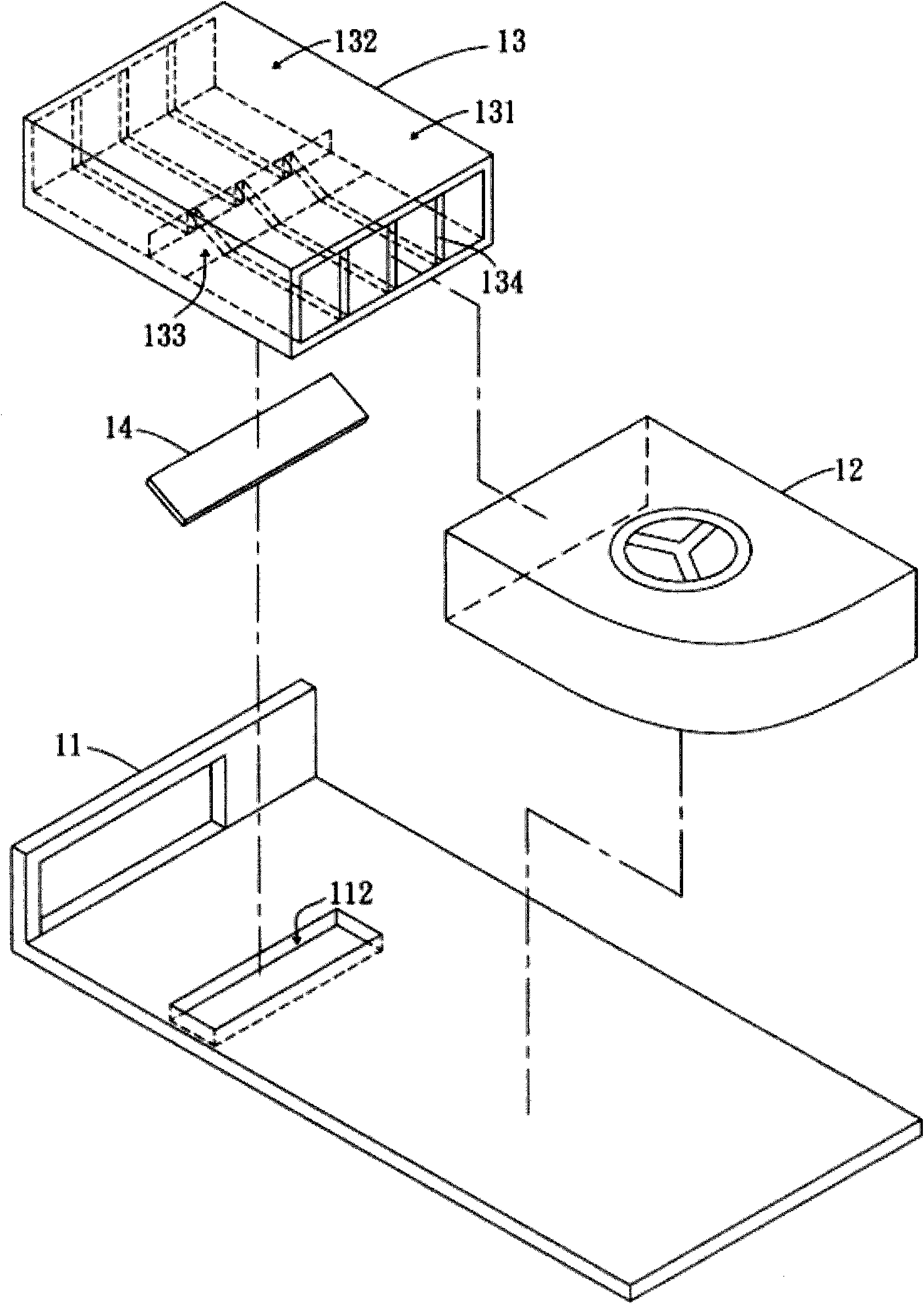
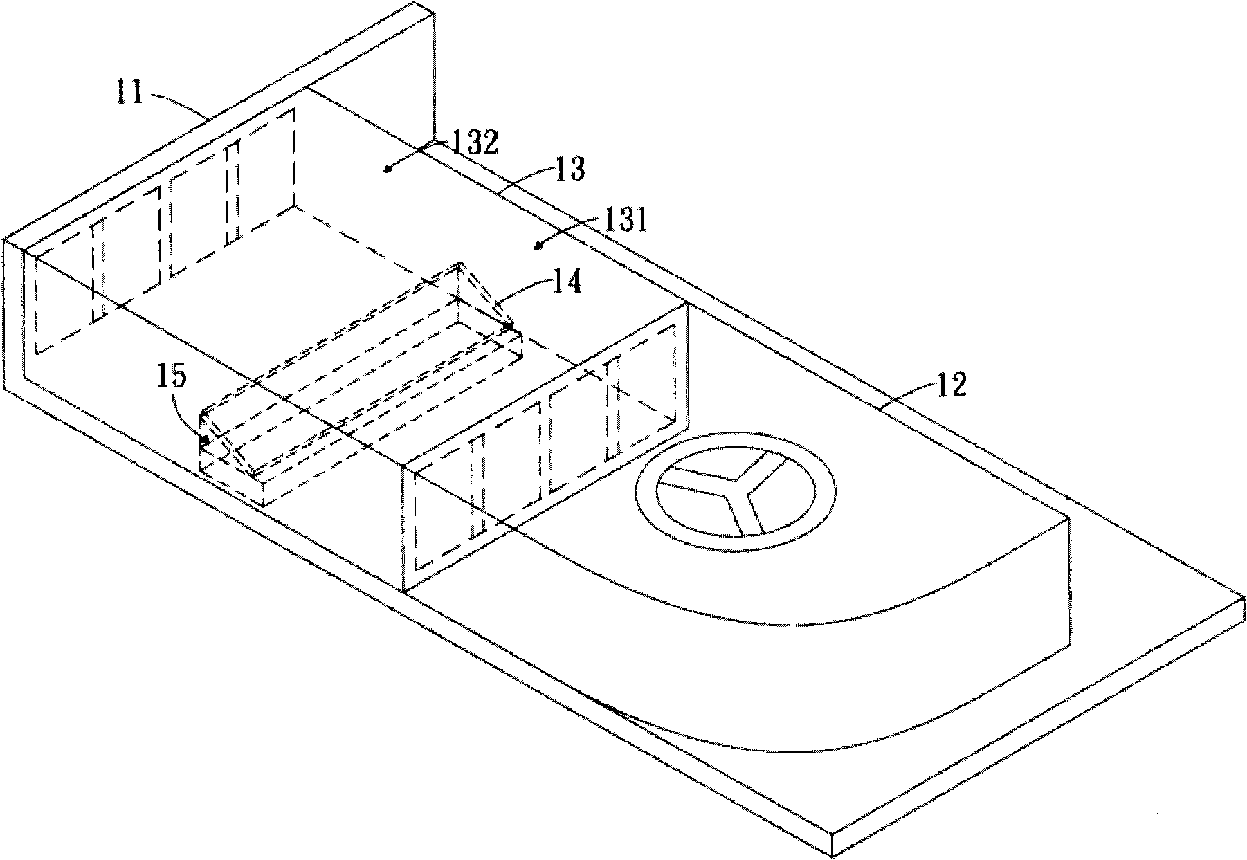
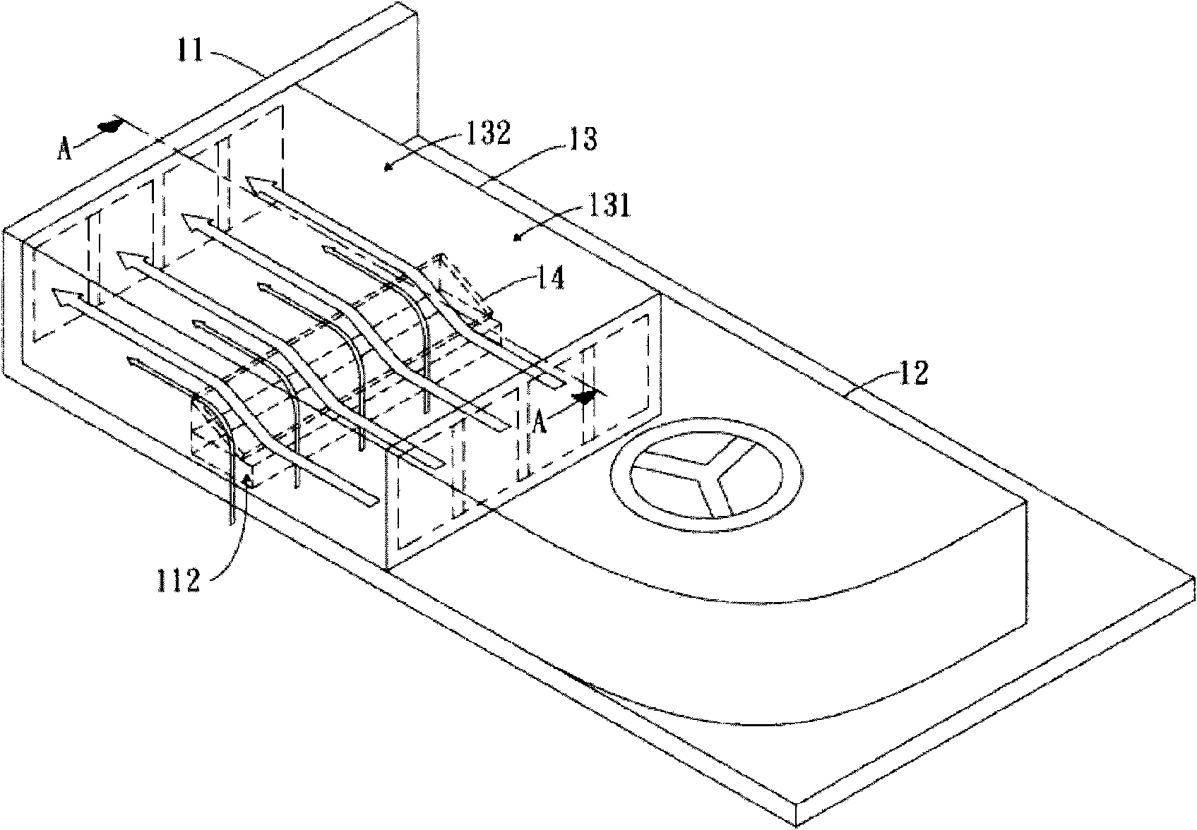
[0022] Please refer to Figure 1A to Figure 1D , are the assembly schematic diagram, perspective view, cooling airflow schematic diagram and cross-sectional view along the A-A section line of the first embodiment of the present invention, respectively. part of the case 11), and a fan 12 is arranged in the case 11 to generate the first cooling airflow F1, this embodiment includes: a heat dissipation assembly 13 and an air deflector 14, wherein the heat dissipation assembly 13 has a first area 131 and The second area 132 has a second opening 133, the first cooling air flow F1 flows from the first area 131 of the heat dissipation assembly 13 to the second area 132, and the air deflector 14 is arranged on the first area 131 of the heat dissipation assembly 13 for use Reduce the cross-sectional area of ​​the first cooling air flow F1...


PUM


Abstract

The invention relates to a device and a method for radiating. The device is arranged inside a casing provided with a first opening, and a fan is used for generating a first cooling airflow. The device comprises a radiating assembly and an air deflector, wherein the radiating assembly is provided with a first area and a second area, and the first cooling air flows from the first area to the secondarea. The air deflector is installed in the first area of the radiating assembly and used for reducing the section area of the first cooling airflow flowing in the first area in the flowing directionof the first cooling airflow so as to suck the air outside the casing to flow into the second area through the first opening to generate a second cooling airflow. Therefore, the temperature of the casing located below the radiating assembly is reduced.

Description

technical field [0001] The invention relates to a heat dissipation device and method, in particular to a heat dissipation device and method capable of reducing the temperature of a casing located below a heat dissipation assembly. Background technique [0002] With the increasing performance of notebook computers, more and more users have abandoned heavy desktop computers and switched to thin and light notebook computers. However, in order to make the performance of notebook computers comparable to desktop computers, the first thing to overcome is It is necessary to effectively dissipate a large amount of heat energy generated by the central processing unit and the computer chip in a very small space. [0003] Common notebook computers use the heat pipe to guide the heat generated by the CPU and the computer chip to the heat dissipation assembly formed by parallel connection of multiple heat sinks, and then use the fan to cool it, so the notebook computer runs for a period o...

Claims


Application Information

Patent Timeline
Patent Type & Authority Applications(China)
IPC IPC(8): H05K7/20G06F1/20H01L23/467
Inventor 张育玮张瑚松锺兆才
Owner PEGATRON
Features
  • R&D
  • Intellectual Property
  • Life Sciences
  • Materials
  • Tech Scout
  • Unparalleled Data Quality
  • Higher Quality Content
  • 60% Fewer Hallucinations
Learn More