Mass-sensitive chemical sensor

A mass-sensitive, chemical-sensing technology, applied in the field of mass-sensitive chemical sensors, which can solve the problems of contamination-sensitive surfaces, sensor inability, removal, etc.

Inactive Publication Date: 2010-03-17
ATTANA AB
View PDF4 Cites 6 Cited by
  • Summary
  • Abstract
  • Description
  • Claims
  • Application Information

AI Technical Summary

Problems solved by technology

If the flow chamber is assembled so that the upper part of the flow chamber mates with the upper side of the flange, the height of the sample chamber can be better controlled, but the sensor will be mounted differently (which depends on the thickness of the adhesive, the weight of the sensor and the bonding time) will still inevitably

Method used


Image

  • Mass-sensitive chemical sensor
  • Mass-sensitive chemical sensor
  • Mass-sensitive chemical sensor

Examples


Embodiment Construction

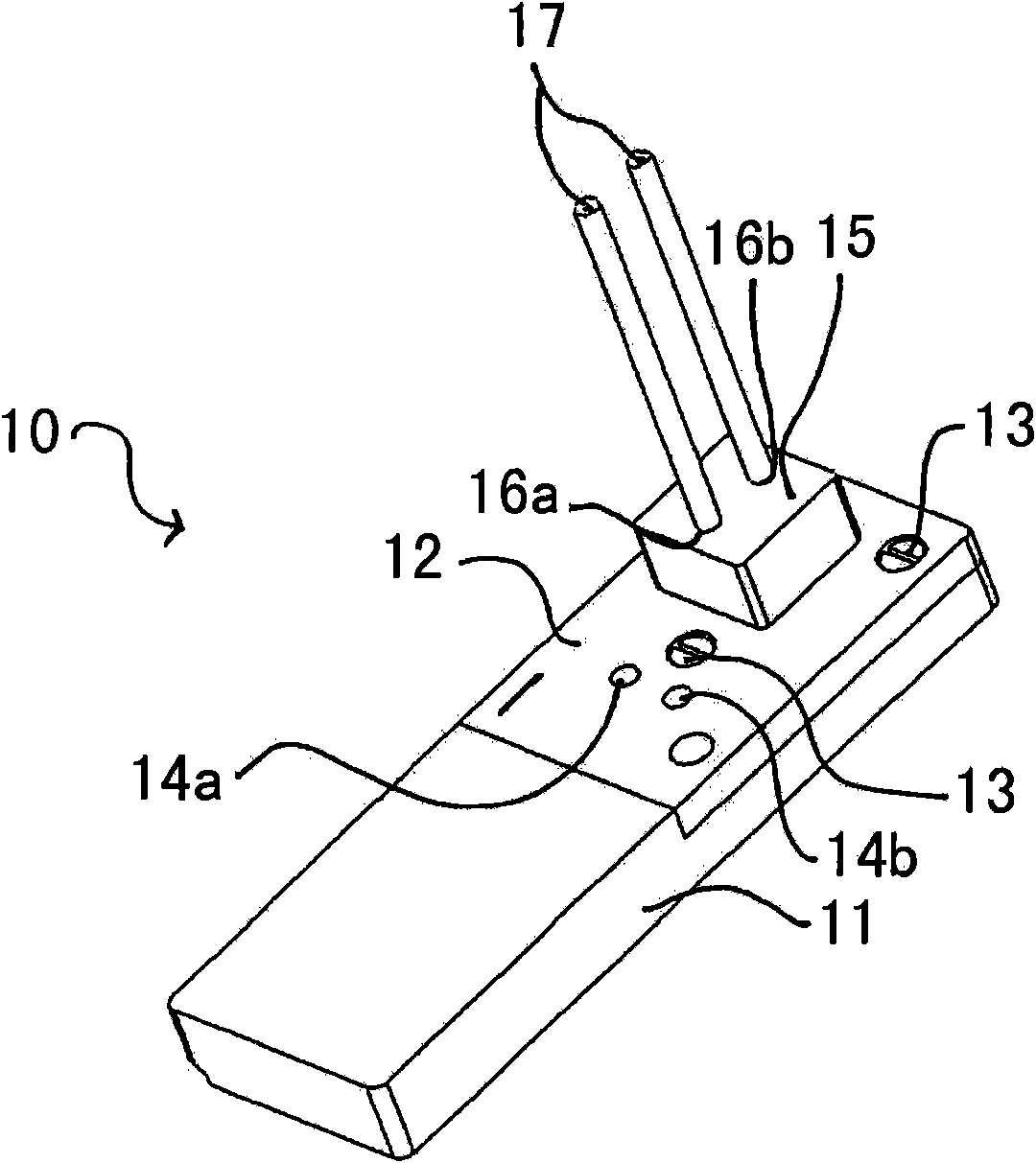
[0095] first reference figure 1 , the sensing element denoted by 10 includes a base part 11 and a cover part 12 connected to the base part 11 by screws 13 . Both the cover part and the base part are formed from the substantially rigid plastic material acetal. The cover part 12 has two holes 14a, 14b for connecting electrical contacts (eg plugs to wires) from a sensing instrument such as the Attana A100QCM instrument. The cover part 12 has connected thereto a rubber gasket 15 having two through holes 16a, 16b. Tubes 17 are connected to the holes 16a, 16b for passing sample fluids, buffers, etc. between the sensing elements and the instrument.

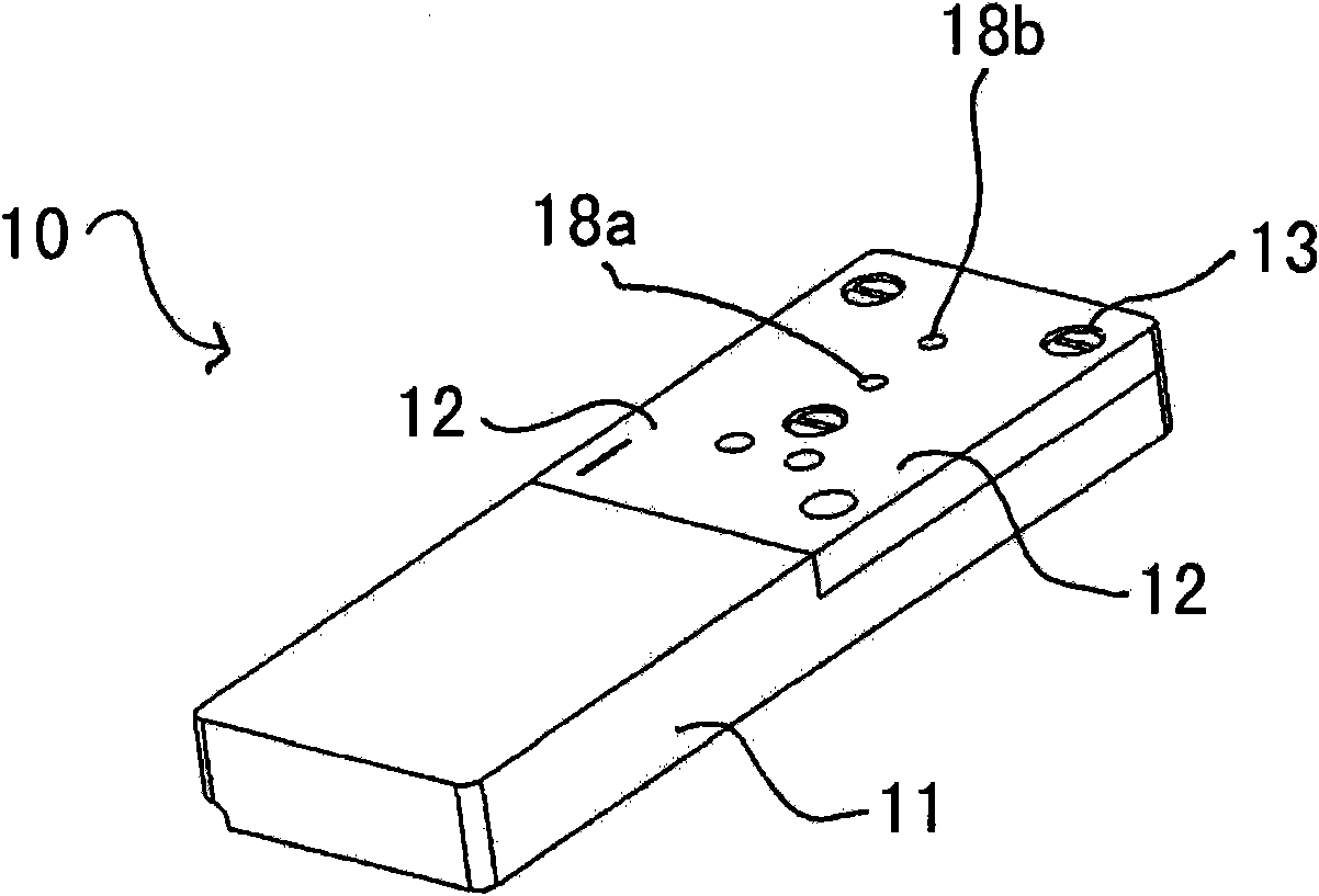
[0096] Remove gasket 15 ( figure 2 with Figure 4 ), it can be seen that the cover part comprises two holes 18a, 18b. The holes 18a, 18b are channels through which a sample fluid or the like can pass and flow into a sensor located in the sensing element, as will be described in detail below.

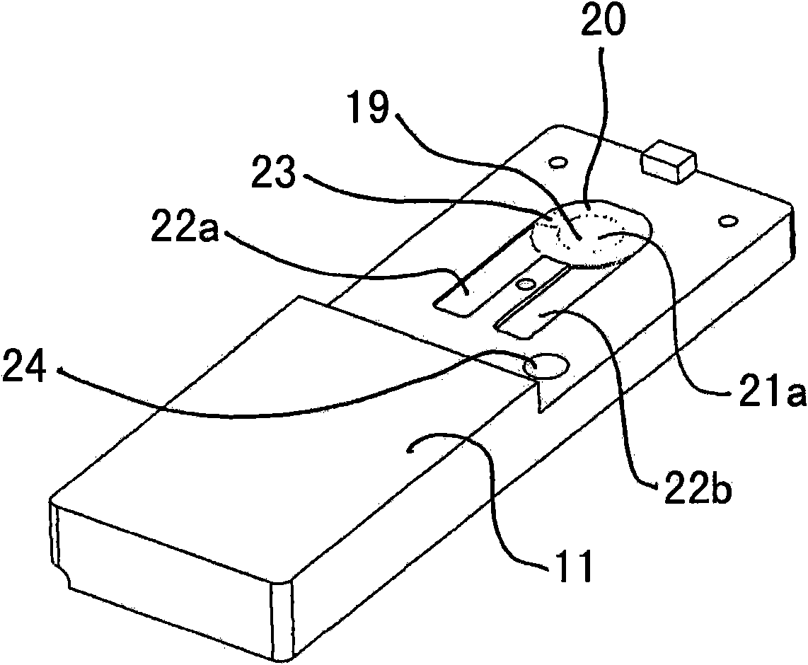
[0097] The QCM sensor 19 is located i...


PUM


Abstract

A sensor element carrier for use in a mass-sensitive chemical sensor instrument comprises a base component and a lid component, the base component being adapted to receive, in use, a sensor, the signal generated by which depends on the mass of material adsorbed at a sensing surface thereof, the base component or the lid component having formed therein, in a recessed area, at least one channel forthe ingress of sample fluid, the recessed area forming, in use and in conjunction with the sensing surface of the sensor, a sample chamber, the sensor being held, in use, between the base component and the lid component and the approach of the base component and lid component being limited on assembly of the sensor element by means of substantially rigid portions of each which come into abutment,thereby limiting the minimum height of the sample chamber for a given set of sensor, base and lid components.

Description

technical field [0001] The invention relates to a mass sensitive chemical sensor. In particular, but not exclusively, it relates to a sensing element and associated auxiliary equipment for use in mass sensitive chemical sensing instruments. Background technique [0002] A mass-sensitive chemical sensor can be defined as any device that allows the measurement of a property proportional to a mass located on or adhered to a sensitive surface of the device. Some of these sensor technologies can be exploited, such as evanescent wave based sensors such as surface plasmon resonance (SPR, which can indicate changes in mass through associated changes in the surface refractive index), optical waveguides (also based on mass adhesion events associated changes in the refractive index), light diffraction, light wave interference, ellipsometric polarization, and acoustic wave devices such as quartz crystal microbalances (QCMs). These sensor methods are well known in the art (see for exam...

Claims


Application Information

Patent Timeline
IPC IPC(8): G01N27/00G01N29/02G01N29/22
CPCG01N29/022G01N2291/0256G01N2291/0255G01N2291/0426G01N29/222
Inventor H·安德森H·比约克曼T·奥斯特鲁普
Owner ATTANA AB
Why Eureka
Try Eureka