Immersion type membrane separation apparatus and method of operating the same

A technology for membrane separation and membrane separation, which is applied in the direction of semipermeable membrane separation, chemical instruments and methods, membranes, etc. It can solve the problems of low sweeping effect of the membrane surface, large reduction of separation membrane filtration function, insufficient cleaning of the membrane surface, etc.

Active Publication Date: 2010-03-24
TORAY IND INC
View PDF4 Cites 12 Cited by
  • Summary
  • Abstract
  • Description
  • Claims
  • Application Information

AI Technical Summary

Problems solved by technology

However, when such a diffuser is used as Figure 15 In the case of the arrangement shown below the separation membrane module, since the central part of the air diffuser cannot emit tiny air bubbles, there is almost no air lift effect, so the sweeping effect on the membrane surface is extremely small
As a result, there is a problem that the membrane surface of the central part of the separation membrane module is insufficiently cleaned compared with other parts, and the filtration function of the separation membrane is greatly reduced.

Method used


Image

  • Immersion type membrane separation apparatus and method of operating the same
  • Immersion type membrane separation apparatus and method of operating the same
  • Immersion type membrane separation apparatus and method of operating the same

Examples


Embodiment 1

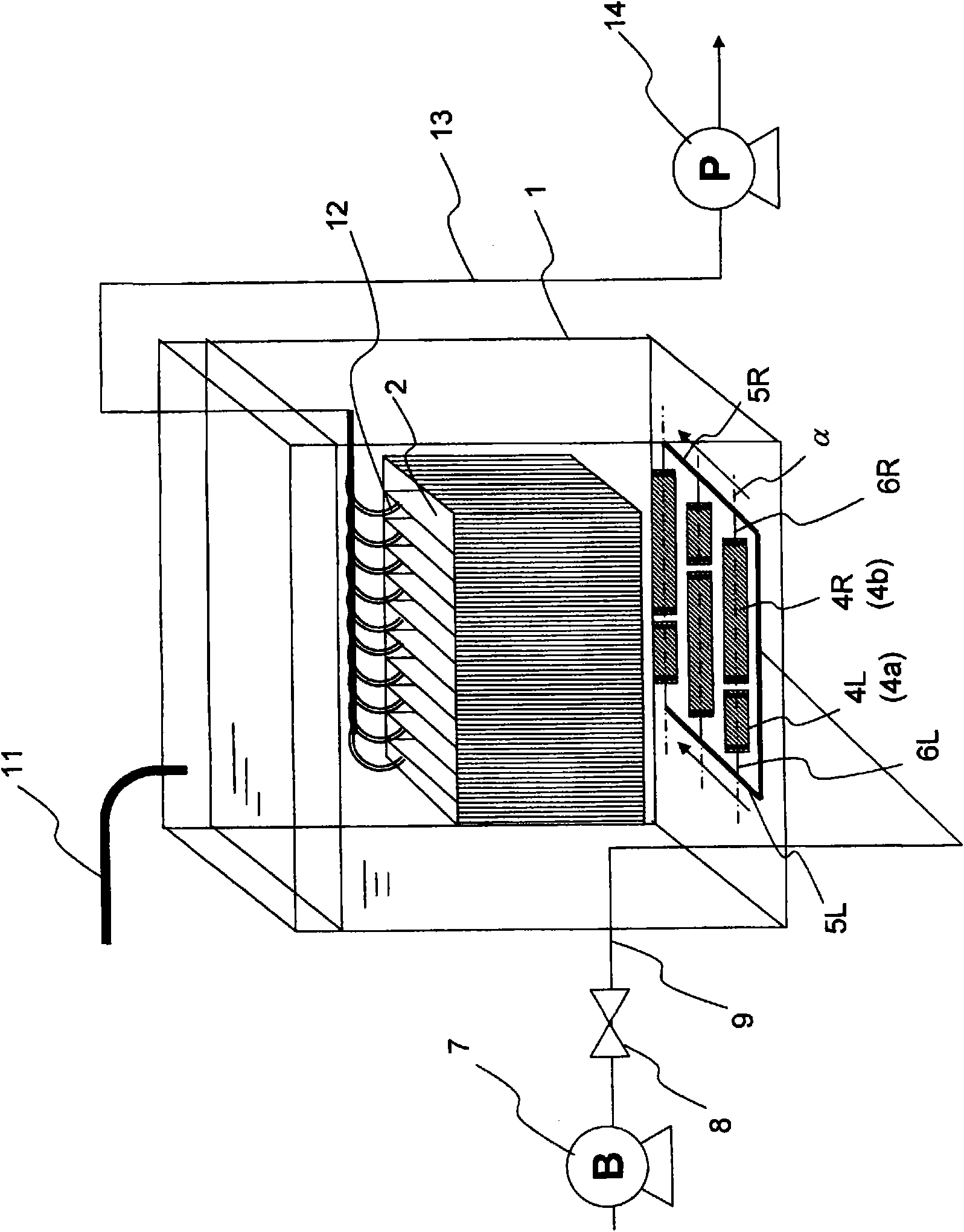
[0122] A specific example of the membrane separation device of the present invention is shown in FIG. 6 . Figure 6(a)(b)(c) are the front view, side view, and A-A sectional view of the membrane separation device, respectively. In this figure, the gas supply pipe and its upstream side are omitted.

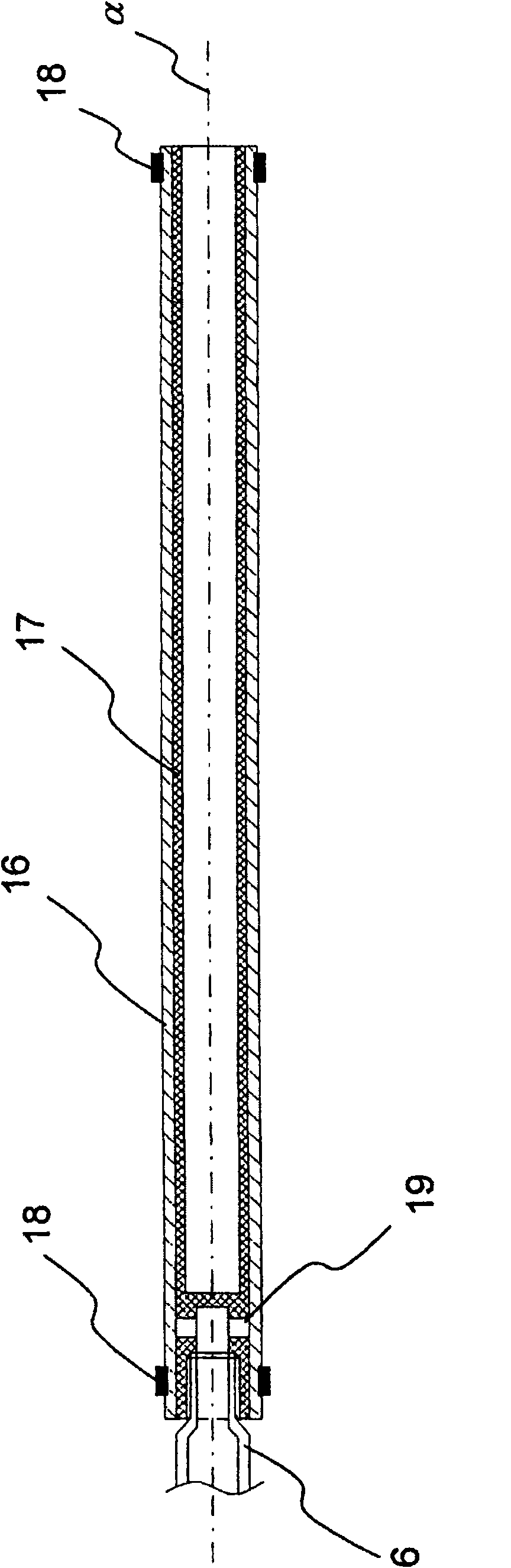
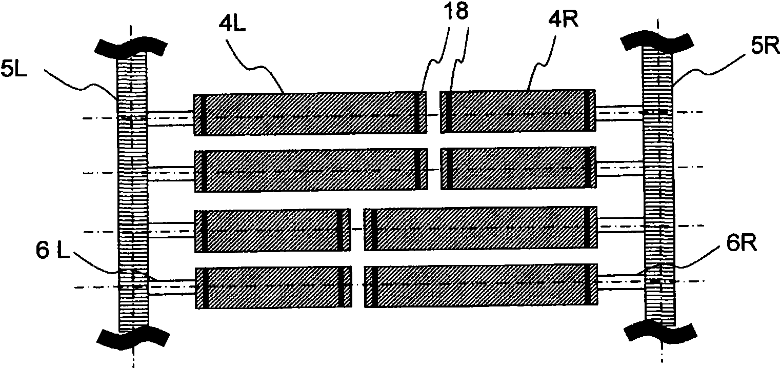
[0123] In this device, 100 separation membrane elements arranged in parallel are arranged in the separation membrane module 2 . Vertically below the separation membrane module 2, there are provided a microbubble diffusion pipe extending horizontally from a branch pipe portion 6R of a gas supply pipe (not shown) on the right side, and a gas supply pipe (not shown) on the left side. ) The branch pipe part 6L is a microbubble diffuser pipe extending in the horizontal direction. The central axes α in the longitudinal direction of these microbubble diffuser tubes are arranged in four rows on substantially the same horizontal plane so that the tips of the microbubble diffuser tubes faci...

Embodiment 2

[0125] Another specific embodiment of the membrane separation device of the present invention is shown in FIG. 7, and FIG. 7(a), (b) and (c) are the front view, side view, and A-A sectional view of the membrane separation device, respectively. In this figure, the gas supply pipe and its upstream side are omitted.

[0126] The structure of the separation membrane module 2 in this device is the same as that of the first embodiment, and the structure of the diffuser pipes arranged below the separation membrane module 2 is different from that of the first embodiment. Vertically below the separation membrane module 2, there are provided a microbubble diffusion pipe extending horizontally from a branch pipe portion 6R of a gas supply pipe (not shown) on the right side, and a gas supply pipe (not shown) on the left side. ) The branch pipe part 6L is a microbubble diffuser pipe extending in the horizontal direction. As these micro-bubble diffuser tubes, all use long micro-bubble diff...

Embodiment 3

[0128] Separation membranes (flat membranes) were installed on the front and back of an ABS support plate (height 1000mm x width 500mm x thickness 6mm) as a substitute for the flow path material, and a membrane element was produced (separation membrane area: 0.9 m 2 ). Here, a flat membrane made of polyvinylidene fluoride having a surface average pore diameter of 0.08 μm and a surface roughness (RMS) of 0.062 μm was used as the separation membrane.

[0129] Next, the inside size (approximate size) was 1000 mm in height x 515 mm in width x 1400 mm in depth, and the box body which opened up and down was manufactured. A frame is connected under the box, and a micro-bubble diffuser tube is fixed at a predetermined position in the space inside the frame. The distance from the lower end of the component to the micro-bubble diffuser tube in the vertical direction is 220mm. At this time, on the side surface parallel to the arrangement direction of the membrane elements, the area of ...


PUM

PropertyMeasurementUnit
pore sizeaaaaaaaaaa
lengthaaaaaaaaaa
lengthaaaaaaaaaa

Abstract

The invention provides an immersion type membrane separation apparatus having a microbubble dispersing tube placed vertically beneath a separation membrane module, in which even when the separation membrane module is of large size, there can be attained all-round uniform generation of microbubbles from an area vertically beneath the separation membrane module. The apparatus comprises a separation membrane module (2) having multiple separation membrane elements each using a flat membrane as a separation membrane disposed in parallel so that the membrane surfaces are parallel to each other; multiple microbubble dispersing tubes (4) placed vertically beneath the separation membrane module; and multiple gas supply tubes (5) for supplying a gas to the microbubble dispersing tubes. The multiple gas supply tubes (5) are arranged so as to be opposite to each other across an area vertically beneath the separation membrane module. The multiple microbubble dispersing tubes (4) connected in communicating relationship to the gas supply tubes are arranged so as to extend in a direction crossing a membrane surface of separation membrane element and so as to realize proximity to each other, or superposition on each other, of the distal ends of the opposite microbubble dispersing tubes.

Description

technical field [0001] The invention relates to a submerged membrane separation device and its operation method which can be applied to the treatment of sewage, excrement, industrial waste water and the like. In particular, it relates to the improvement of the structure of the diffuser pipe in the submerged membrane separation device. Background technique [0002] In the past, as a water treatment device that uses a membrane to filter sewage, excrement, industrial wastewater, etc., such as Figure 15 A submerged membrane separation device installed in a treatment tank as shown is submerged. exist Figure 15 In the process, the submerged membrane separation device is immersed in the liquid to be treated stored in the treatment tank 1 . A permeate water outlet 12 is provided in the filtration membrane module 2 in which a plurality of flat-plate filtration membranes are arranged in parallel so that the membrane surfaces are parallel, and a treated water pipe 13 communicates wi...

Claims


Application Information

Patent Timeline
Patent Type & Authority Applications(China)
IPC IPC(8): B01D63/08B01D65/02C02F1/44C02F3/20
CPCB01D2315/06C02F3/1273B01D61/18B01D2313/26B01D2321/185B01D63/082Y02W10/10B01D63/0821B01D63/0822
Inventor 高畠宽生成濑麻美杉田和弥北中敦
Owner TORAY IND INC
Why Eureka
Try Eureka