
Fuel pump

A technology of fuel pumps and fuel oils, applied in the direction of pumps, pump components, cross-flow pumps, etc., can solve the problems of surface treatment tolerances, high manufacturing costs of fuel pumps, etc., and achieve the effects of avoiding damage, high strength, and small manufacturing tolerances

Inactive Publication Date: 2010-03-24
CONTINENTAL AUTOMOTIVE GMBH
View PDF0 Cites 0 Cited by
  • Summary
  • Abstract
  • Description
  • Claims
  • Application Information

AI Technical Summary

Problems solved by technology

However, the installation of the insert after the surface treatment of the housing parts leads to very high manufacturing costs of the fuel pump
In addition, the surface treatment of the housing parts causes tolerances, which are problematic, for example, for pressing inserts into housing parts

Method used


Image

  • Fuel pump
  • Fuel pump

Examples


Embodiment Construction

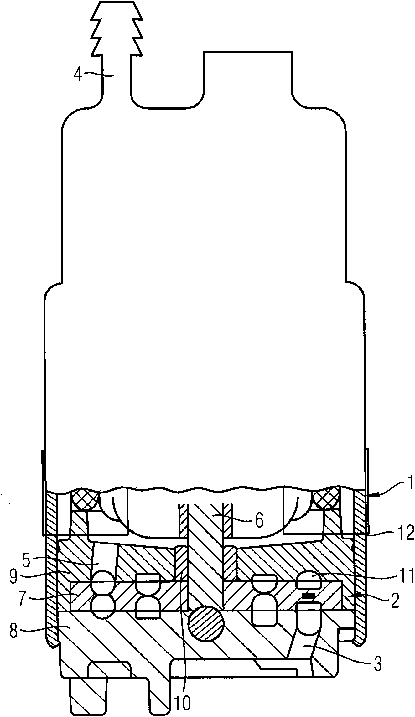
[0014] figure 1 A fuel pump is shown with a pump stage 2 driven by an electric motor 1 . The fuel pump has an inlet 3 arranged on the pump stage 2 and an outlet bushing 4 arranged on the side of the electric motor 1 facing away from the pump stage 2 . The fuel sucked in through the inlet 3 of the pump stage 2 is delivered to the outlet sleeve 4 via the electric motor 1 via the outlet 5 of the pump stage 2 . A drain line, not shown, leading to the internal combustion engine can be connected to the outlet sleeve 4 . The pump stage 2 has an impeller 7 fastened to the shaft 6 of the electric motor 1 and is designed as a side-channel pump. The impeller 7 is held rotatably between the two housing parts 8 , 9 of the pump stage 2 . For mounting the shaft 6 an insert 10 is fastened in one of the housing parts 9 as a bearing sleeve. One of the housing parts 8 has an inlet 3 and the other housing part 9 has an outlet 5 . The impeller 7 and the housing parts 8 , 9 have a delivery cha...


PUM


Abstract

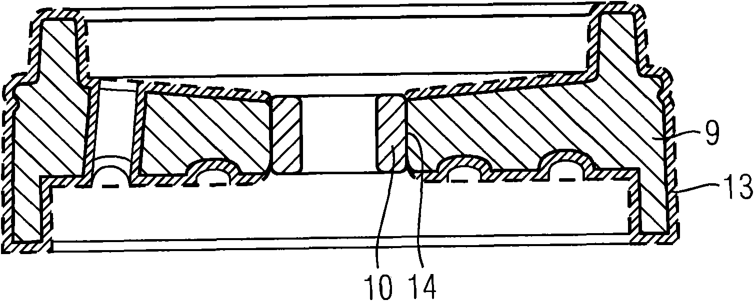
A fuel pump for delivering fuel has a housing part (8) made from a coated material. An insert (10) made from an electrically non-conductive material, such as for example phenolic resin, is pressed into the housing part (8). The insert (10) which is produced from phenolic resin can be pressed into the housing part (8) before a surface treatment of the housing part (8), since phenolic resin is not electrically conductive. As a result, the fuel pump can be produced particularly inexpensively.

Description

technical field [0001] The invention relates to a fuel pump for delivering fuel, comprising: a housing part for supporting the pump stages and / or for supporting an electric motor driving the pump stages; and an insert fixed in the housing part, wherein the housing Components are made of surface-treated metal. Background technique [0002] Such fuel pumps are frequently used in modern motor vehicles and are known from practice for feeding fuel from a fuel tank to an internal combustion engine of the motor vehicle. In known fuel pumps, the inserts are mostly made of carbon or graphite. To manufacture the fuel pump, the housing parts are first machined and surface treated by means of electric current. After surface treatment, one or several inserts are fixed in the housing part and the entire assembly is reworked. This ensures that the insert is neither coated nor damaged by aggressive media or currents in a tank for surface treatment. In particular, it has been found that ...

Claims


Application Information

Patent Timeline
Patent Type & Authority Applications(China)
IPC IPC(8): F02M37/04
CPCF04D29/026F02M37/048F02M37/08F04D29/2227F04D29/046F04D5/002F05D2300/43F05D2300/12F05D2300/611F05D2300/70F02M37/04
Inventor 马蒂亚斯·菲舍尔克里斯托夫·施密特
Owner CONTINENTAL AUTOMOTIVE GMBH
Learn More