
Brushless motor

一种无刷电动机、定子的技术,应用在电动组件、电气元件、机电装置等方向,能够解决对齐、难外部定子和磁极传感器位置、外部定子需要电绝缘性等问题,达到确保电绝缘性、提高位置精度的效果

Inactive Publication Date: 2010-03-24
MITSUBISHI ELECTRIC CORP
View PDF4 Cites 20 Cited by
  • Summary
  • Abstract
  • Description
  • Claims
  • Application Information

AI Technical Summary

Problems solved by technology

Therefore, it is difficult to align the positions of the external stator and the magnetic pole sensor since the positions of the external stator and the magnetic pole sensor are determined in the final assembly process
Also, since the magnetic pole sensor is generally constituted by a chip or the like, there is a problem that electrical insulation etc. are required with respect to the external stator

Method used


Image

  • Brushless motor
  • Brushless motor
  • Brushless motor

Examples


Embodiment approach 1

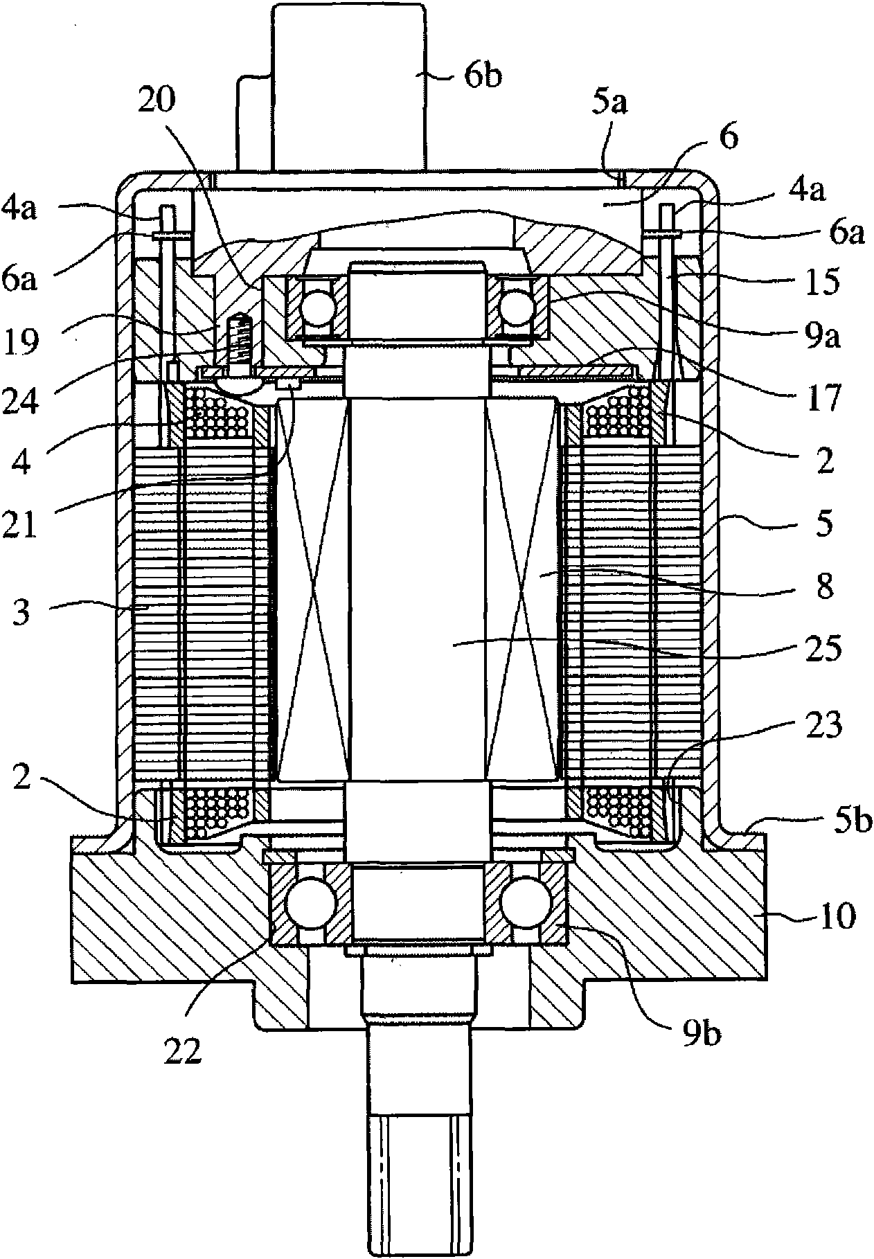
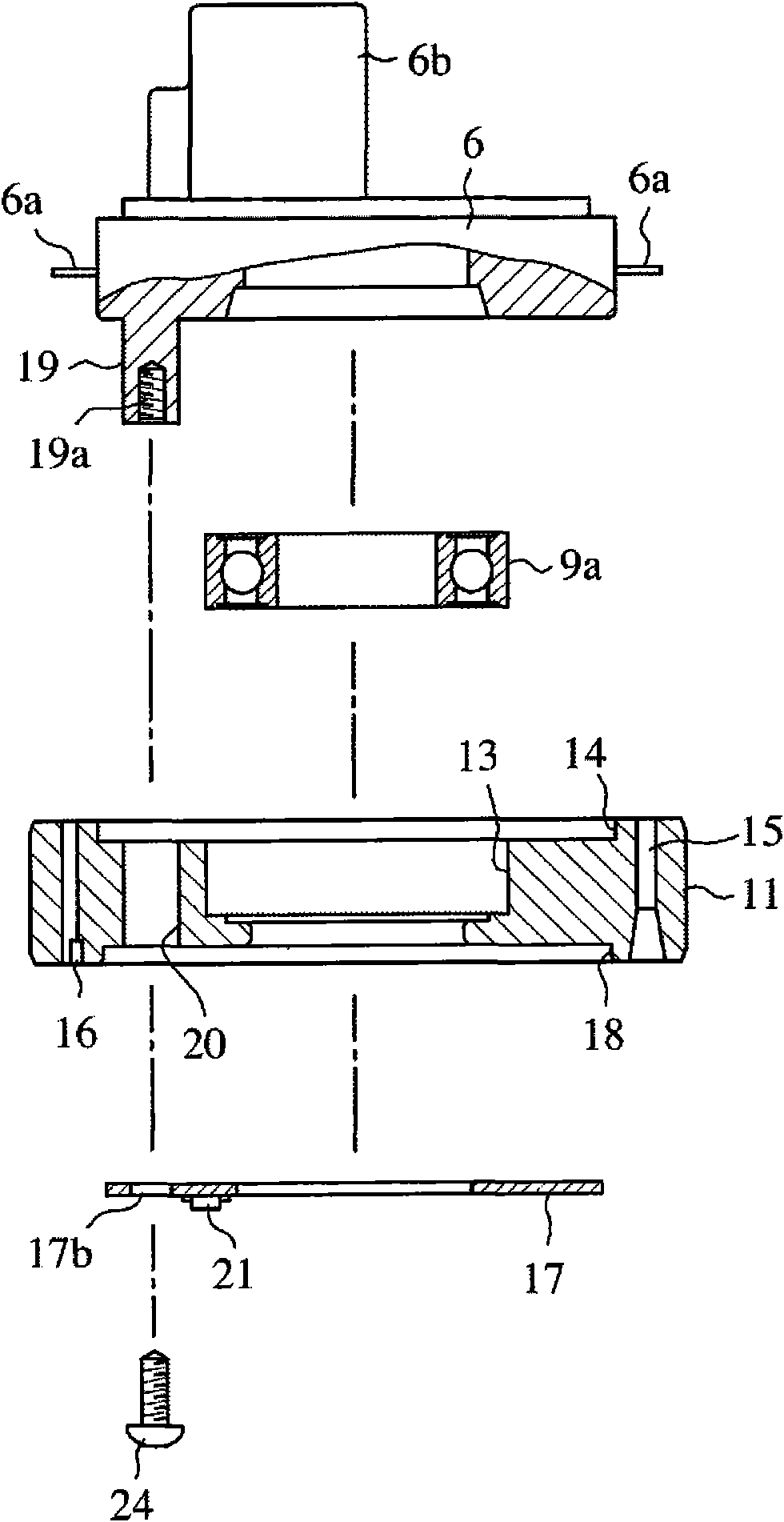
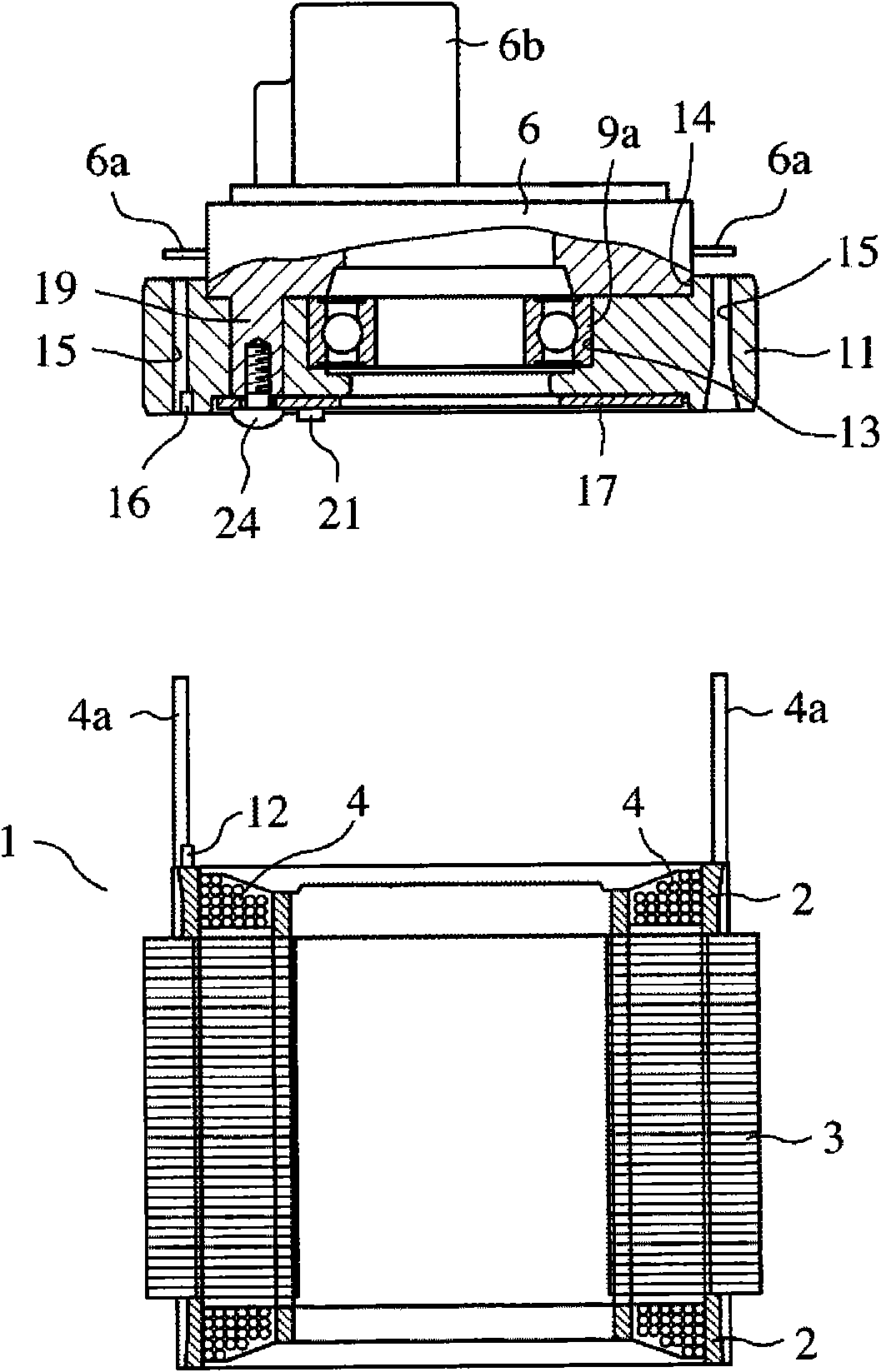
[0022] figure 1 is a longitudinal sectional view showing the brushless motor according to Embodiment 1 of the present invention; figure 2 is an exploded perspective view of components mounted on one end side of the outer stator; image 3 yes means figure 2 A longitudinal sectional view of the relationship between the assembly of the constituent parts and the external stator; Figure 4 is said to be figure 2 A longitudinal sectional view of a state in which the assembly of constituent parts and the external stator are assembled; Figure 5 is an enlarged view of the main part showing the relationship between the winding end passing through the through hole of the insulating plate and the bus bar terminal; Image 6 yes means Figure 4 A longitudinal sectional view of the relationship between the integrated structure and the outer shell; Figure 7 It is a longitudinal cross-sectional view showing the relationship between the outer stator and the case in which the inner ro...


PUM


Abstract

In a brushless motor comprising an external stator constituted by electrically forming a magnetic circuit by winding wire on a core, a bus bar forming an external input terminal by tying the wound wire together, and an internal rotor integrated with a permanent magnet and rotatably supported to the external stator through bearings, an insulating plate is held at one end side of the external stator, and a magnetic pole sensor for detecting the magnetic pole of the permanent magnet is attached to the insulating plate.

Description

technical field [0001] The present invention relates to a brushless motor used as a driving source of, for example, an EGR (Exhaust Gas Recirculation) valve, a VG (Variable Geometry, variable geometry) turbine actuator, and the like. Background technique [0002] The brush motor (commutator motor) uses a commutator to switch the electrical contacts mechanically. Unlike the brushless motor, the direction of the current is switched from the controller side, so in order to switch the direction of the current , It is necessary to detect the magnetic poles of the permanent magnets used in the inner rotor of the brushless motor. In order to simplify this magnetic pole detection and reduce costs, a magnetic pole sensor such as a Hall element is used. [0003] Therefore, in the past, the axial length of the permanent magnet used in the inner rotor was extended to the position where the magnetic pole sensor could detect the magnetic pole (Patent Document 1); or other magnets and magn...

Claims


Application Information

Patent Timeline
Patent Type & Authority Applications(China)
IPC IPC(8): H02K29/08
CPCH02K29/08H02K5/15H02K3/50H02K5/04H02K15/16H02K5/1732H02K5/225
Inventor 衣川浩行菅原济文
Owner MITSUBISHI ELECTRIC CORP
Learn More