Heat-radiation packaging structure and packaging method

A technology of packaging structure and packaging method, applied in electrical components, electrical solid devices, circuits, etc., can solve the problems of high heat dissipation and high density of semiconductors, limited heat conduction efficiency, and imperfect heat dissipation effect.

Inactive Publication Date: 2010-03-31
何昆耀
View PDF0 Cites 4 Cited by
  • Summary
  • Abstract
  • Description
  • Claims
  • Application Information

AI Technical Summary

Problems solved by technology

However, due to the use of MCPCB as a heat dissipation medium, the heat conduction efficiency is limited, so that the heat dissipation effect is not perfect, and the volume of the h

Method used


Image

  • Heat-radiation packaging structure and packaging method
  • Heat-radiation packaging structure and packaging method
  • Heat-radiation packaging structure and packaging method

Examples


Embodiment Construction

[0024] The present invention proposes a heat-dissipating packaging structure and packaging method, using copper metal substrates to achieve good heat-dissipating effects and light and thin features. Below, the heat-dissipating packaging structure and packaging method with leads are used as examples to describe the present invention in detail. technical characteristics.

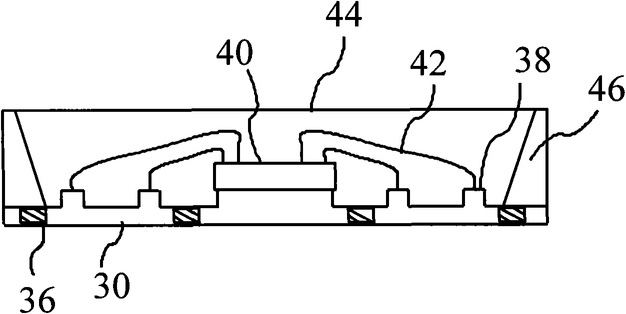
[0025] figure 2 Shown is a cross-sectional view of the structure of the first embodiment of the present invention, as shown in the figure, a metal substrate 30 has a plurality of conductive contacts 38, and a plurality of insulators 36 are arranged inside the metal substrate 30, which are located on the conductive contacts 38. Between the contacts 38; a chip 40 is mounted on the surface of the metal substrate 30, and the chip 40 is electrically connected to the conductive contacts 38 via a plurality of leads 42; at least one reflector 46 is positioned around the metal substrate 30 for use To increase the ref...


PUM


Abstract

The invention discloses a heat-radiation packaging structure and a packaging method which utilize a metal basal plate. The metal basal plate is provided with a plurality of conductive joints, a plurality of insulators, at least one chip, at least one light reflecting mirror and a packaging colloid, wherein the insulators are positioned in the metal basal plate and are arranged between the conductive joints; the chip is installed at the surface of the metal basal plate and is electrically connected with the conductive joints by a plurality of leading wires, and heat energy generated by the chipis dispersed by the metal basal plate; the light reflecting mirror is arranged at the periphery of the metal basal plate and increases the reflection efficiency of a light source; and the packaging colloid covers and protects the metal basal plate. The invention can maintain a favorable heat-radiation effect, simplify the packaging structure and the manufacturing procedure, and lower the production cost.

Description

【Technical field】 [0001] The invention relates to a semiconductor packaging technology, in particular to a heat dissipation packaging structure and a packaging method. 【Background technique】 [0002] In the early heat dissipation packaging structure, the copper foil printed circuit board was directly used as the heat dissipation medium, and the FR4 printed circuit board was most commonly used. However, as the component density becomes higher and higher, the speed requirements become faster and the power consumption of the assembled components is higher and higher, the heat energy will increase more and more, because the thermal conductivity of the FR4 printed circuit board is insufficient , so that it is gradually difficult to meet the heat dissipation requirements. [0003] Therefore, another metal core printed circuit board (Metal Core PCB, MCPCB) packaging structure that can effectively improve the heat dissipation problem has been proposed, such as figure 1 As shown, t...

Claims


Application Information

Patent Timeline
IPC IPC(8): H01L23/488H01L23/367H01L23/373H01L21/50H01L21/60
CPCH01L2924/01019H01L2924/01046H01L2224/48091H01L2224/48247
Inventor 何昆耀
Owner 何昆耀
Why Eureka
Try Eureka