Vacuum processing system and substrate transfer method

A technology for vacuum processing and substrates, applied in vacuum evaporation plating, conveyor objects, ion implantation plating, etc., can solve the problems of reduced productivity and time-consuming, and achieve the effect of preventing cross-contamination

Inactive Publication Date: 2010-03-31
TOKYO ELECTRON LTD
View PDF2 Cites 11 Cited by
  • Summary
  • Abstract
  • Description
  • Claims
  • Application Information

AI Technical Summary

Problems solved by technology

[0005] However, the pressure levels required in PVD processing and CVD processing generally differ by more than 10,000 times, and it is necessary to set the transfer chamber to a higher pressure when

Method used


Image

  • Vacuum processing system and substrate transfer method
  • Vacuum processing system and substrate transfer method
  • Vacuum processing system and substrate transfer method

Examples


Embodiment Construction

[0022] Hereinafter, embodiments of the present invention will be specifically described with reference to the drawings.

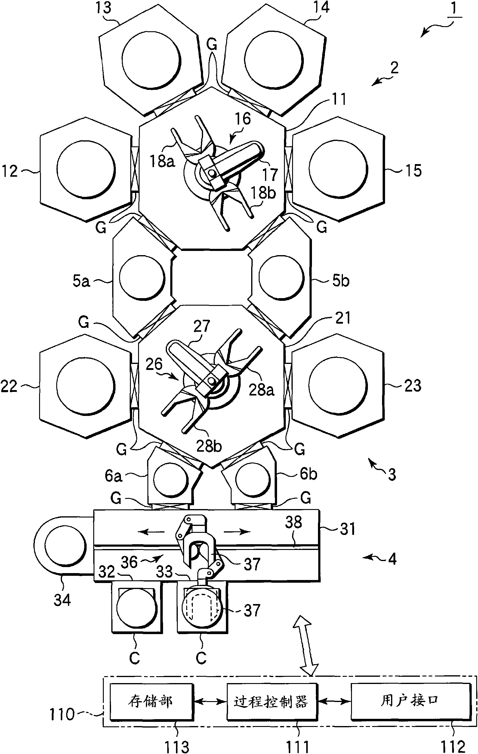
[0023] figure 1 It is a plan view showing a multi-chamber vacuum processing system according to an embodiment of the present invention.

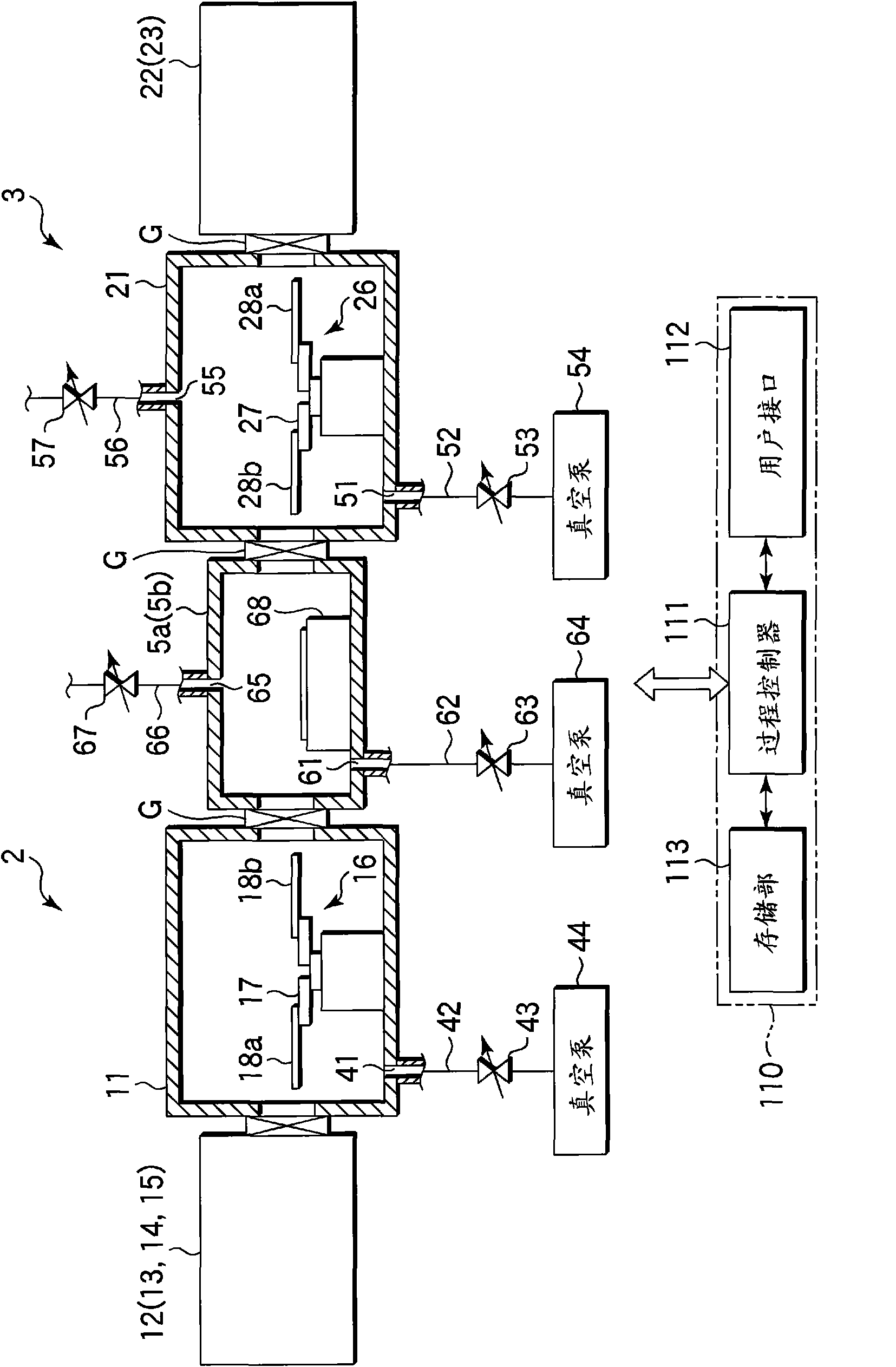
[0024] The vacuum processing system 1 has: a first processing unit 2 with a plurality of processing chambers for processing under high vacuum (low pressure), namely PVD processing, such as sputtering; The second processing part 3 of the chamber; the loading and unloading part 4; membrane.

[0025] The first processing unit 2 has a first transfer chamber 11 having a heptagonal planar shape, and four PVD processing chambers 12 , 13 , 14 , and 15 connected to four sides of the first transfer chamber 11 . On the other two sides of the first transfer chamber 11, the above-mentioned buffer chambers 5a, 5b are respectively connected. The PVD processing chambers 12-15 and the buffer chambers 5a, 5b are connected to each side ...


PUM


Abstract

A vacuum processing system (1) is provided with a first processing section (2) wherein PVC processing chambers (12-15) are connected to a first transfer chamber (11) to which a wafer (W) is to be transferred; a second processing section (3) wherein CVD processing chambers (22, 23) are connected to a second processing chamber (21) to which the wafer is to be transferred; a buffer chamber (5a), which is arranged between the first transfer chamber (11) and the second transfer chamber (12) through a gate valve (G), stores the wafer (W), and is capable of adjusting pressure therein; and a control section (110) for controlling opening/closing of a gate valve (G) and pressure in the buffer chamber (5a) so that the buffer chamber (5a) is selectively communicated with either the first transfer chamber (11) or the second transfer chamber (12) and that pressure inside matches with pressure inside the communicating transfer chamber.

Description

technical field [0001] The present invention relates to a vacuum processing system in which a processing chamber is arranged in a transfer chamber capable of maintaining a vacuum, and a substrate transfer method in the vacuum processing system. Background technique [0002] In the manufacturing process of a semiconductor device, a process of forming a plurality of metal or metal compound films is performed on a semiconductor wafer (hereinafter simply referred to as wafer) as a substrate to be processed in order to form a contact structure or a wiring structure. This type of film formation process is carried out in a process chamber kept in vacuum. However, recently, from the viewpoint of effective processing and suppression of contamination such as oxidation and pollutants, the following cluster tool (cluster tool) type A chamber system attracts attention, that is, a plurality of processing chambers are connected to a transfer chamber kept in a vacuum, so that wafers can be ...

Claims


Application Information

Patent Timeline
IPC IPC(8): C23C14/56C23C16/44H01L21/285H01L21/3205H01L21/677
CPCC23C14/566C23C16/54H01L21/67196H01L21/67184C23C16/4401
Inventor 宫下哲也平田俊治原正道
Owner TOKYO ELECTRON LTD
Why Eureka
Try Eureka