Optical fiber light trap acceleration measurement device

A technology of acceleration measurement and optical fiber, which is applied in the fields of inertial measurement technology and optical engineering, can solve problems such as the influence of measurement accuracy and uneven distribution of light intensity, and achieve the effects of improving measurement accuracy, increasing beam waist diameter, and reducing process difficulty

Inactive Publication Date: 2010-04-07
ZHEJIANG UNIV
View PDF0 Cites 14 Cited by
  • Summary
  • Abstract
  • Description
  • Claims
  • Application Information

AI Technical Summary

Problems solved by technology

[0004] The disadvantage of this device is that the laser output from the fiber is a fundamental-mode Gaussian beam with uneven light intensity distribution.
Due to the uneven distribution of light intensity, the gradient force pointing to the strong light intensity is two orders of magnitude larger than the

Method used


Image

  • Optical fiber light trap acceleration measurement device
  • Optical fiber light trap acceleration measurement device
  • Optical fiber light trap acceleration measurement device

Examples


Embodiment Construction

[0021] Further illustrate the present invention below in conjunction with accompanying drawing.

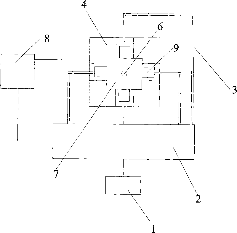
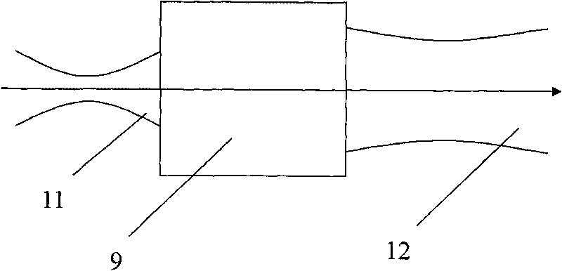
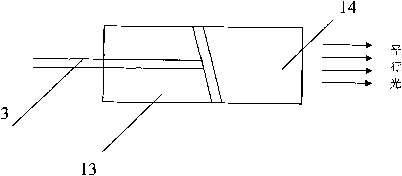
[0022] ginseng figure 1 As shown, the optical fiber optical trap acceleration measurement device of the present invention includes a laser 1, a light intensity modulator 2, four single-mode optical fibers 3, an optical fiber fixing substrate 4 provided with a "cross" shaped groove, and is packaged in a "cross" shaped groove. Clear solution at the intersection of the tank 5 ( figure 1 not visible in ) and a spherical particle 6 , a photoelectric image detector 7 , a processor 8 and four optical elements 9 within the transparent solution 5 . The light emitted by the laser 1 is modulated by the light intensity modulator 2 into four beams of light with the same light intensity, and then input into four single-mode optical fibers 3 respectively, and the four single-mode optical fibers 3 are respectively coupled into the corresponding optical elements 9, and the four optical elements ...


PUM

PropertyMeasurementUnit
Particle sizeaaaaaaaaaa

Abstract

The invention discloses an optical fiber light trap acceleration measurement device, belonging to the fields of inertia measurement technology and optical engineering. Four optical elements in the measurement device are arranged in a cross groove of an optical fiber fixing substrate respectively; transparent solution is capsulated in the crossing position of the cross groove; the output end face of the optical element is aligned with spherical particles in the transparent solution, the distance between output end faces of two opposite optical elements is between 50 and 800 microns; output ends of four monomode optical fibers are coupled in corresponding optical elements respectively, while input ends thereof are connected with a light intensity modulator; light emitted by a laser is modulated into four beams of light with the same light intensity through the light intensity modulator, and the four beams of light are input into the four monomode optical fibers respectively; an photoelectric image detector is arranged right above the cross position of the cross groove; and the photoelectric image detector and the light intensity modulator are respectively connected with a processor. The device has the advantages of even light intensity distribution and small radial gradient force, has high measurement sensitivity, and reduces the requirement on alignment accuracy of the beam.

Description

[0001] Technical Field The present invention relates to a four-beam fiber optic trap acceleration measurement device, which belongs to the fields of inertial measurement technology and optical engineering. Background technique [0002] According to quantum theory, a light beam is a group of photon streams moving at the speed of light and having both mass and momentum. When the light beam is refracted and reflected on the surface of the medium, the speed and direction of the photon change, resulting in a change in its momentum vector. According to the law of conservation of momentum, the change in momentum of photon is equal to the change in momentum of particle. Therefore, the momentum of the particle changes accordingly, that is, the effect of the light beam on the particle, which is called the light radiation pressure. Studies have shown that the light radiation pressure includes the scattering force along the beam propagation direction and the gradient force always pointin...

Claims


Application Information

Patent Timeline
IPC IPC(8): G01P15/03
Inventor 胡慧珠董希杰舒晓武刘承
Owner ZHEJIANG UNIV
Why Eureka
Try Eureka