
Power frequency zero-flux mini-current sensor for capacitive equipment dielectric loss on-line monitoring

A technology of capacitive equipment and zero magnetic flux, which is applied in the direction of measuring current/voltage, measuring electric variables, voltage/current isolation, etc., can solve the problems of complex sensor structure, difficulty in manufacturing and high cost, and achieve simple internal structure and good performance. On-site anti-interference ability and high reliability effect

Inactive Publication Date: 2011-05-04
西安博源电气有限公司
View PDF1 Cites 0 Cited by
  • Summary
  • Abstract
  • Description
  • Claims
  • Application Information

AI Technical Summary

Problems solved by technology

Although the dynamic zero-flux state of the sensor is also realized, the structure of the sensor is complex, and the main magnetic core and the auxiliary magnetic core must have the same magnetization characteristics and dimensions, making it difficult and costly to manufacture

Method used

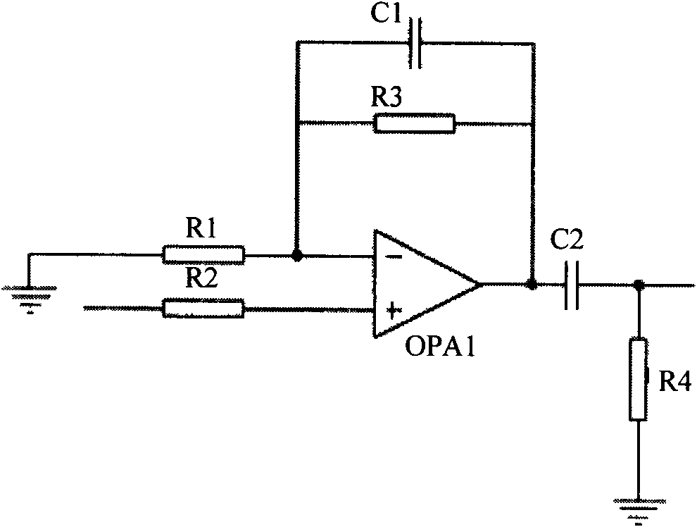
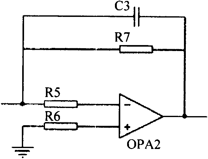

Image

  • Power frequency zero-flux mini-current sensor for capacitive equipment dielectric loss on-line monitoring
  • Power frequency zero-flux mini-current sensor for capacitive equipment dielectric loss on-line monitoring
  • Power frequency zero-flux mini-current sensor for capacitive equipment dielectric loss on-line monitoring

Examples


Embodiment Construction

[0025] The structural principle and working principle of the present invention will be further described in detail below in conjunction with the accompanying drawings.

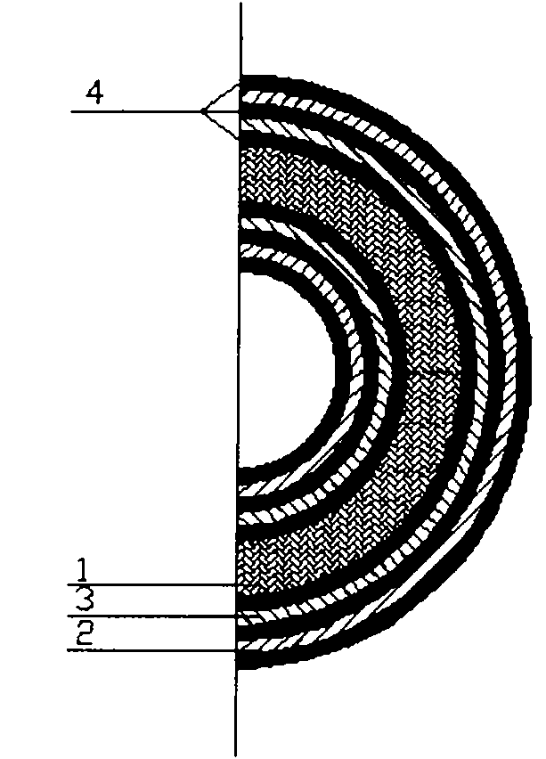
[0026] refer to figure 1 The internal physical structure of a power frequency zero-flux small current sensor for on-line monitoring of dielectric loss of capacitive equipment includes a working magnetic core 1 on which a secondary side coil 2 and a detection coil 3 are wound. The specific winding structure is to use enameled wire to wind the detection coil 3 on the working magnetic core 1, and then use the enameled wire to wind the secondary side coil 2 in the opposite direction on the detection coil 3, between the secondary side coil 2 and the detection coil 3, A shielding layer 4 is provided between the detection coil 3 and the working magnetic core 1 .

[0027] refer to figure 2 , is a schematic diagram of the sensor principle of the present invention, wherein the detection coil 3 is connected to the com...


PUM


Abstract

A power frequency zero-flux mini-current sensor for capacitive equipment dielectric loss on-line monitoring comprises a working magnetic core 1, wherein a test coil 3 is winded round the working magnetic core 1, a secondary side coil 2 is winded round the test coil 3 in the inverse direction, shielding layers 4 are arranged between the secondary side coil 2 and the test coil 3, and the test coil 3 and the working magnetic core 1, the test coil 3 is connected with a compensation circuit module 5, the output end of the compensation circuit module 5 is connected with one end of the secondary side coil 2, the other end of the secondary side coil 2 is connected with an output circuit module 6, the two ends of the test coil 3 generate induced potential, the induced current is added to the output end of the compensation circuit module 5 to generate secondary current for the secondary side coil 2, the compensation circuit module 5 is used to test the potential difference of the test coil 3, the magnetic flux in the working magnetic core is almost equal to zero; and if the test value deviates the permissible value, the working magnetic core can be adjusted automatically to keep in almost zero-flux state, and the mini-current sensor has high reliability and is characterized by simple structure, little production difficulty and low cost.

Description

technical field [0001] The invention relates to the field of current sensors for electrical measurement, in particular to a power frequency zero-flux small current sensor for on-line monitoring of the dielectric loss of capacitive equipment. Background technique [0002] The safe operation of high-voltage power transmission and transformation equipment is an important factor affecting the safety, stability and economic operation of the power system. Insulation accidents in high-voltage equipment will not only cause damage to the equipment itself, but also cause various losses. Transformation equipment such as coupling capacitors, capacitive bushings, current transformers, and capacitive voltage transformers can be regarded as capacitive equipment composed of multiple capacitors connected in series. They add up to about half of the power transmission and transformation equipment. [0003] With the development of the smart grid, the online monitoring of the insulation paramet...

Claims


Application Information

Patent Timeline
Patent Type & Authority Patents(China)
IPC IPC(8): G01R19/00G01R15/18G01R27/26
Inventor 韩元斌梁红军王长安
Owner 西安博源电气有限公司
Learn More