
Heavy-load type oil-gas spring independent suspension steering drive axle

A technology of steering drive axle and oil-pneumatic spring, which is applied in the field of machinery, can solve problems such as the inability to adjust the ground clearance, affect the handling performance of the vehicle, and affect the stiffness of the entire bridge, etc., to achieve improved maneuverability and stability, compact structure, and improved structure. The effect of stiffness

Inactive Publication Date: 2012-05-23
BEIJING INST OF SPACE LAUNCH TECH
View PDF6 Cites 0 Cited by
  • Summary
  • Abstract
  • Description
  • Claims
  • Application Information

AI Technical Summary

Problems solved by technology

However, when driving on uneven roads, the left and right wheels affect each other, and the camber angle of the wheels changes greatly, which affects the handling performance of the vehicle; and when adjusting the height of the frame, the ground clearance cannot be adjusted
In addition, the oil and gas spring independent suspension disclosed in ZL200610164840.7 has the lower suspension point arranged on one side of the lower cross arm instead of the center of the whole bridge, which may cause uneven force and affect the stiffness of the whole bridge, thereby affecting the bearing capacity.

Method used


Image

  • Heavy-load type oil-gas spring independent suspension steering drive axle
  • Heavy-load type oil-gas spring independent suspension steering drive axle
  • Heavy-load type oil-gas spring independent suspension steering drive axle

Examples


Embodiment Construction

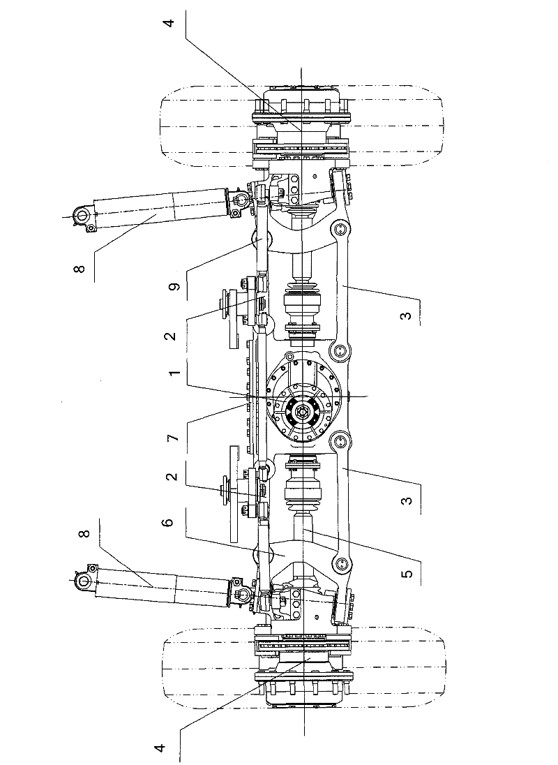
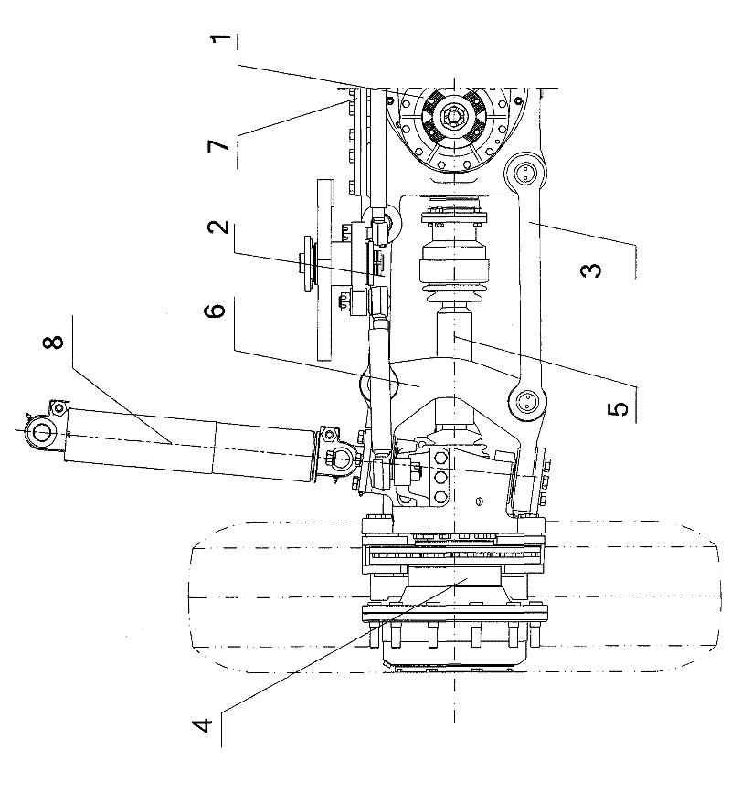
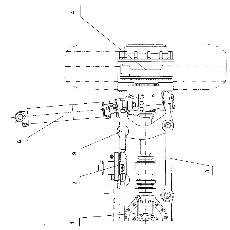
[0033] The invention as Figure 1-6 As shown, it includes central main reducer assembly 1, upper cross arm 2, lower cross arm 3, wheel side reducer assembly 4, double ball cage type constant velocity universal joint transmission shaft 5, steering knuckle seat 6, oil-gas spring 8 and the steering rod system 9, the central final reducer assembly 1 is located at the center of the steering drive axle and is fixedly connected to the vehicle frame 7, the upper cross arm 2, the lower cross arm 3, the wheel side reducer assembly 4, and the double ball cage The constant velocity universal transmission shaft 5, the steering knuckle seat 6 and the oil-pneumatic spring 8 are symmetrically distributed at both ends of the central final drive assembly 1, and the left and right structures are exactly the same.

[0034] Central main reducer assembly 1 such as Figure 7 As shown, it includes a housing 11 , a differential device 12 and an input flange 13 . The central final reducer assembly 1 ...


PUM


Abstract

The invention relates to a heavy-load type oil-gas spring independent suspension steering drive axle which comprises a central main reducing gear assembly, an upper cross arm, a lower cross arm, a hub reducing gear assembly, a double-rzeppa type constant velocity universal transmission shaft, a steering joint seat, an oil-gas spring and a steering rod system, wherein the central main reducing gear assembly is located in the center of the steering drive axle and fixedly connected to a frame, and structures of the heavy-load type oil-gas spring independent suspension steering drive axle at the left end and the right end of the central main reducing gear assembly are the same and symmetrically distributed. The steering joint seat is adopted, thus stress in the front, back, left and right directions of the whole steering drive axle trends to be more uniform and reasonable, the steering drive axle has higher traveling smoothness and better maneuverability, and the regulation of ground clearance can be realized at the same time of regulating the height of the frame. The upper cross arm and the lower cross arm of the heavy-load type oil-gas spring independent suspension steering drive axle are respectively of an integral structure, thereby improving the structural rigidity. Both ends of the upper cross arm and the lower cross arm are respectively connected with the steering joint seat and a main reducing gear shell through pin shafts, and the reasonable optimization of swing arm connection points ensures that the changes of wheel tracks and wheel inclination angles are the minimum when wheels jump up and down to the limit, thereby improving the controllabitity and the stability of a chassis.

Description

technical field [0001] The invention relates to an independent suspension steering drive axle, in particular to an oil-pneumatic spring independent suspension steering drive axle for multi-axis super-heavy construction machinery vehicles, and belongs to the field of mechanical technology. Background technique [0002] At present, construction machinery vehicles represented by all-terrain cranes generally adopt oil-pneumatic spring non-independent suspensions. The suspension device adopts the layout form of oil-pneumatic springs as elastic elements, thrust rods as guide devices, and integral axles as load-bearing devices. The suspension device with this structure has better ride comfort, and can also realize the adjustment of the height of the vehicle frame. However, when driving on uneven roads, the left and right wheels affect each other, and the camber angle of the wheels changes greatly, which affects the handling performance of the vehicle; and when adjusting the height ...

Claims


Application Information

Patent Timeline
Patent Type & Authority Patents(China)
IPC IPC(8): B60G11/28B60G3/18
Inventor 张斌吴学雷葛铠单红波伊曙东胡文俊左霞罗小江苏善德
Owner BEIJING INST OF SPACE LAUNCH TECH
Learn More