Tunnel kiln waste heat boiler

A waste heat boiler and tunnel kiln technology, applied in the field of waste heat boilers, can solve the problem of how to heat when there is no waste heat or insufficient waste heat, and achieve the effects of reducing combustion costs, simplifying production processes, and reducing fuel varieties

Inactive Publication Date: 2010-04-14
袁奕明
View PDF0 Cites 5 Cited by
  • Summary
  • Abstract
  • Description
  • Claims
  • Application Information

AI Technical Summary

Problems solved by technology

On the other hand, during the production of the tunnel kiln, a large amount of hot air is generated due to the cooling of the products, and the waste heat has not been fully utilized except for drying the embryos of the products. If this part of the waste heat can be used to heat the boiler to generate steam for heating Fuel oil can not only save energy and reduce emissions, but also eliminate the need for additional coal-fired boilers, reduce fuel types, simplify production processes, and reduce combustion costs. However, the existing technology has not yet been realized. In addition, there is no waste heat in tunnel kiln ignition or other reasons. Or when the waste heat is insufficient, how to heat the waste heat boiler to generate steam for heating fuel oil is also a technical problem that must be solved at the same time

Method used


Image

  • Tunnel kiln waste heat boiler
  • Tunnel kiln waste heat boiler
  • Tunnel kiln waste heat boiler

Examples


Embodiment Construction

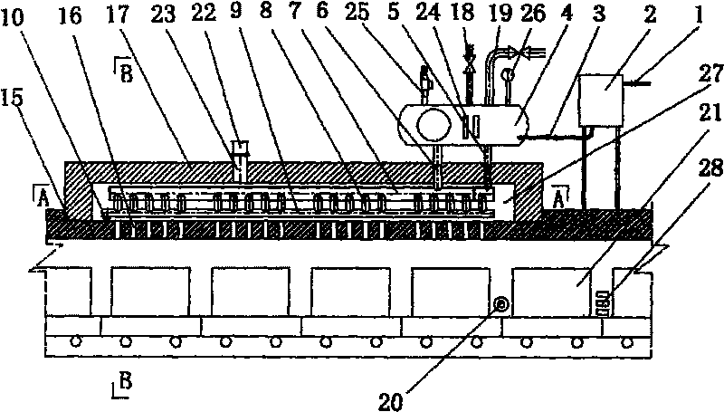
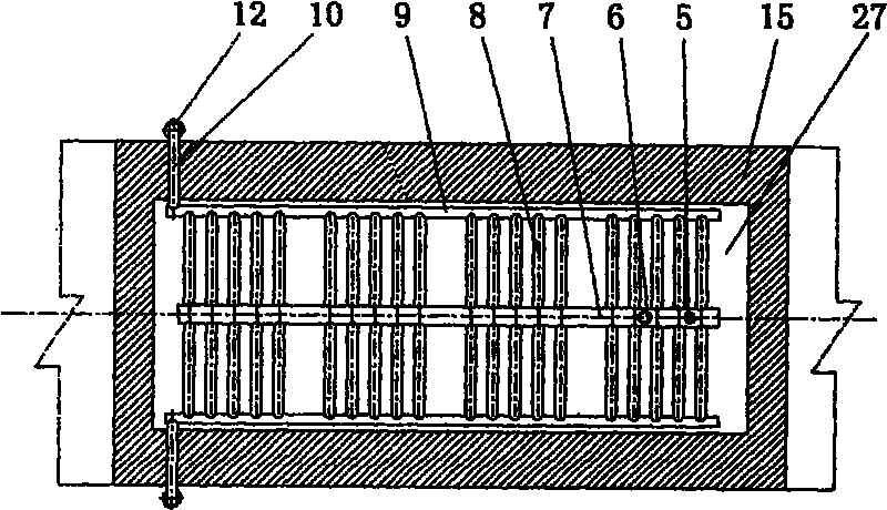
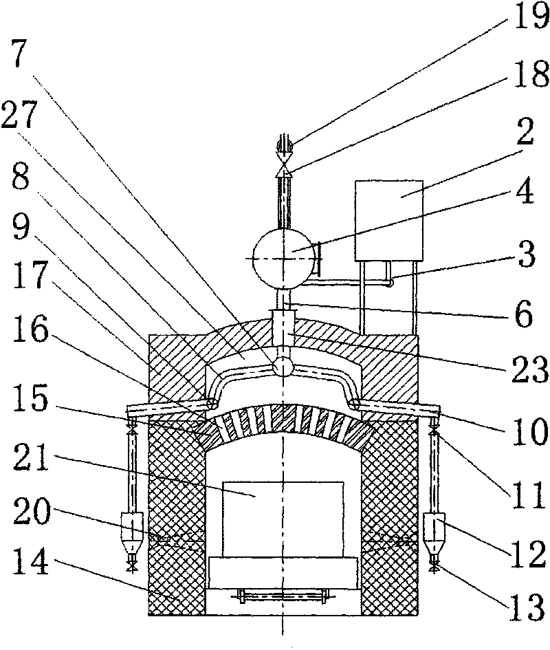
[0013] The tunnel kiln waste heat boiler of the present invention is realized in this way, which will be described in detail below in conjunction with the accompanying drawings. In the present invention, a multi-tube vaporization pot and a masonry hot air furnace are arranged on the kiln roof of the tunnel kiln cooling zone, and a pair of temporary burner burners are added to the walls on both sides of the tunnel kiln cooling zone between the blast hole at the kiln tail and the hot air hole. . See figure 1 , figure 2 , set the water supply pipeline to the roof of the tunnel kiln cooling zone kiln, the water supply valve 1 connected to the water supply pipeline is connected to the water valve 2 with a pipeline, and the bottom of the water valve 2 is connected to the valve 3 and the steam storage tank 4 in turn through the pipeline, and at the bottom of the steam storage tank 4 The steam output pipe 19 with a valve and the steam discharge pipe 18 with a valve are connected on...


PUM


Abstract

The invention relates to a tunnel kiln waste heat boiler which is characterized in that a water supply pipeline is connected to a water supply tank, the bottom of the water supply tank is sequentially connected with valves and a steam storage tank by pipelines; a steam output pipe provided with the valve and a steam discharge pipe provided with the valve are connected on the steam storage tank, and the bottom surface of the steam storage tank is connected with an upper pipe of a multi-pipe evaporation pot by a thick connecting pipe and a thin connecting pipe; and the multi-pipe evaporation pot is formed by the upper pipe, an arc-shaped pipe, a lower pipe and a drain pipe. An inner arch top of a tunnel kiln cooling zone is built with an outer arch top with a certain distance from the inner arch top, the inner arch top is provided with a grate hole which is used for pumping hot air and communicated with the interior of a tunnel kiln, the outer arch top is provided with a hot air suction hole which is communicated with a suction pipe of a hot air pumping machine by the pipeline to form a hot air furnace, and the multi-pipe evaporation pot is positioned inside the hot air furnace. The tunnel kiln waste heat boiler realizes energy conservation and emission reduction, and replaces a coal burning boiler by the waste heat boiler, thus reducing the fuel varieties, simplifying the production technique and lowering the burning cost.

Description

technical field [0001] The invention belongs to a waste heat boiler of a high-temperature tunnel kiln for burning refractory products, in particular to a tunnel kiln waste heat boiler. Background technique [0002] At present, domestic high-temperature tunnel kilns used for firing refractory products have a firing temperature above 1500°C, and most of them use high-viscosity fuel oil as fuel. In order to achieve rapid and complete combustion of fuel oil entering the kiln, it is necessary to heat the fuel oil to Reduce its viscosity so that its Engel's viscosity is controlled at about 5° when it is ejected from the burner. This just must set up coal-fired boiler to produce steam separately, is used for heating fuel oil. On the other hand, during the production of the tunnel kiln, a large amount of hot air is generated due to the cooling of the products, and the waste heat has not been fully utilized except for drying the embryos of the products. If this part of the waste hea...

Claims


Application Information

Patent Timeline
Patent Type & Authority Applications(China)
IPC IPC(8): F27D17/00F22B1/18
CPCY02P10/25
Inventor 袁奕明
Owner 袁奕明
Why Eureka
Try Eureka