Clamp mechanism for processing piston pin hole of compressor

A piston pin hole and compressor technology, which is applied to metal processing machinery parts, manufacturing tools, metal processing equipment, etc., can solve the problems of difficult control of compression force, unreliable compression, poor clamping reliability, etc., and achieve convenient operation , Avoid piston swimming, reliable clamping effect

Inactive Publication Date: 2010-04-21
CHANGSHU INSTITUTE OF TECHNOLOGY
View PDF0 Cites 14 Cited by
  • Summary
  • Abstract
  • Description
  • Claims
  • Application Information

AI Technical Summary

Problems solved by technology

[0004] The above-mentioned jig mechanism has the advantages of simple structure, but there are the following technical problems: the one is that the base 1 is non-adjustable, and because the previous process of the piston 4 is in the process of semi-finishing the outer circle of the piston, the It is objectively very difficult to eliminate the cylindricity error of the outer circle, which will cause the positioning error of the piston 4, and finally cause the verticality of the piston pin hole to be out of tolerance, and easily cause the piston 4 to be scrapped; the second is the effect of the pressing plate 2 on the pressing force. The contact mode between the bottom and the outer circle of the piston is shown as a line contact, more specifically, a point contact, and the clamping reliability of the piston 4 by the pressure plate 2 is poor, so that the piston located between the base 1 and the pressure plate 2 is easy to The third is that the handle 3 is arranged on one of the pair of guide posts in a threaded m

Method used


Image

  • Clamp mechanism for processing piston pin hole of compressor
  • Clamp mechanism for processing piston pin hole of compressor
  • Clamp mechanism for processing piston pin hole of compressor

Examples


Embodiment Construction

[0021] In order to enable the examiners of the patent office, especially the public, to understand the technical essence and beneficial effects of the present invention more clearly, the applicant will describe in detail below in conjunction with the accompanying drawings in the form of embodiments, but none of the descriptions of the embodiments is a description of the present invention. Restriction of the inventive solution, any equivalent transformation made according to the concept of the present invention which is only in form but not in substance shall be regarded as the scope of the technical solution of the present invention.

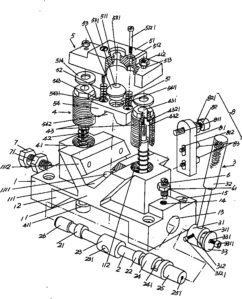
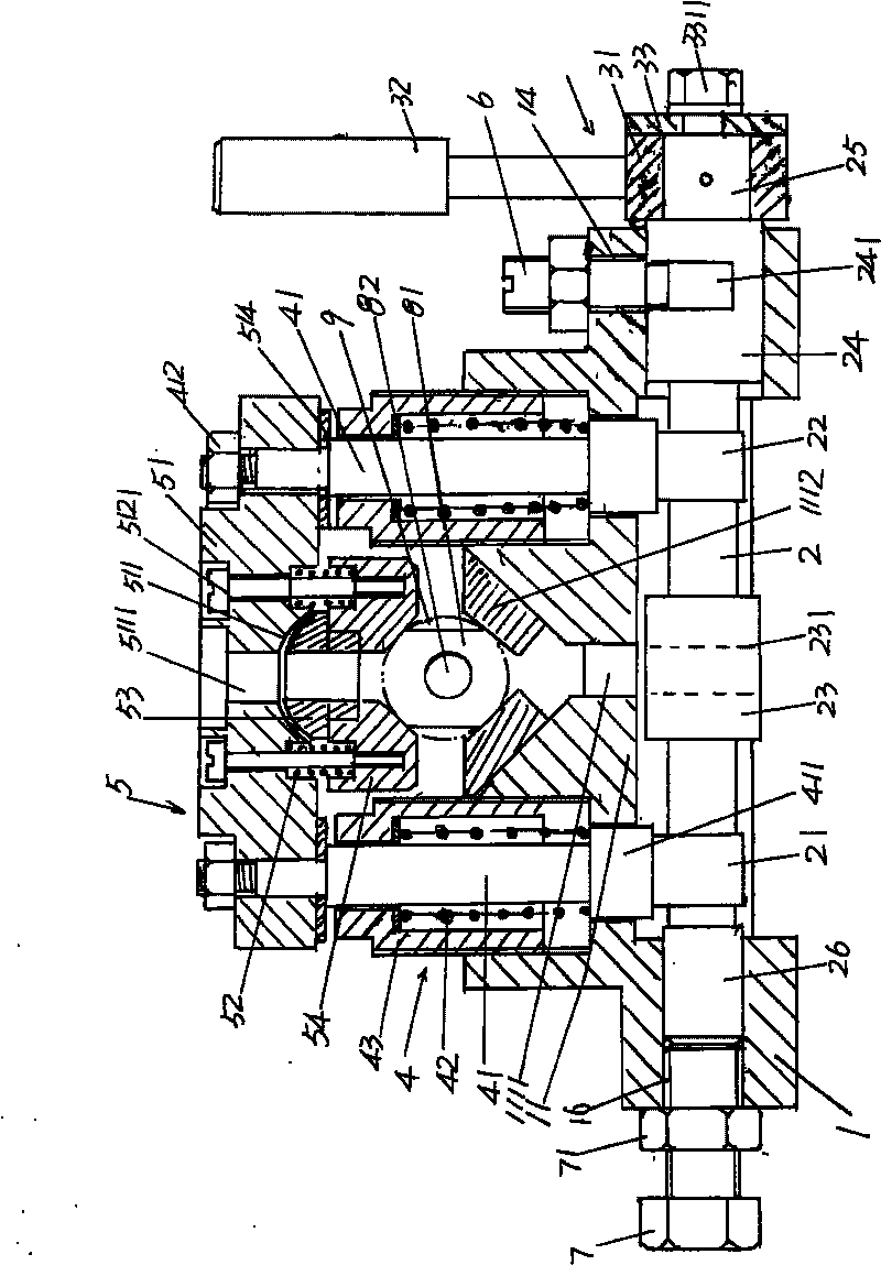
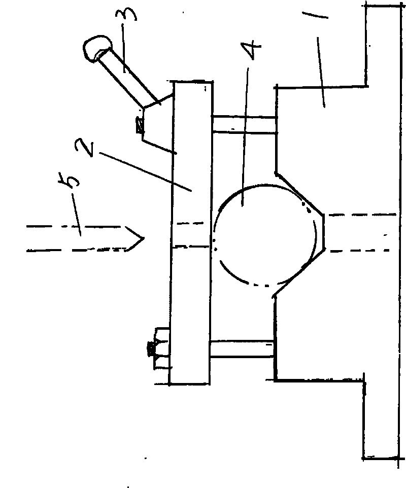
[0022] please see figure 1 with figure 2 , the base 1 preferably processed by metal material is given, and the preferred shape of the base 1 is a rectangle, and the more preferred shape is a cuboid. Depend on figure 1As shown, each of the four corners of the base 1 is provided with a mounting hole 15, and the base 1 is positioned on a workb...


PUM


Abstract

The invention relates to a clamp mechanism for processing a piston pin hole of a compressor, and belongs to the technical field of frock clamps. The clamp mechanism comprises a substrate, a cam shaft, a cam shaft control device, a pair of spherical pair lifting gears and a spherical pair hold-down gear, wherein the bottom of the substrate is provided with a cam cavity; the upper part of the substrate is provided with a workpiece seat; the workpiece seat is provided with a workpiece cavity; the bottom of the workpiece cavity is provided with a cutter through hole; both ends of the cam shaft are rotationally arranged on the substrate; the middle part of the cam shaft corresponds to the inside of the cam cavity; the cam shaft control device is linked with an end part of the cam shaft; the pair of spherical pair lifting gears corresponding to each other is arranged on the workpiece seat of the substrate and corresponds to both sides of the workpiece cavity; lower parts of the pair of spherical pair lifting gears extend into the cam cavity, are in contact with the cam shaft and are actuated by the cam shaft; and the spherical pair hold-down gear is linked with upper parts of the spherical pair lifting gears. The clamp mechanism for processing the piston pin hole of the compressor not only guarantees to reliably clamp a piston to avoid the piston moving about, but also avoids damaging the piston and avoids the deformation of a clamped position of the piston, and has convenient operation.

Description

technical field [0001] The invention belongs to the technical field of fixtures, and in particular relates to a fixture mechanism for processing piston pin holes of compressors. Background technique [0002] Fixtures play a very important role in the production of industrial products, and the processing of piston pin holes for compressor pistons is no exception. The so-called fixture refers to the special equipment or tool used to clamp or position the workpiece in machining to meet certain process requirements. Fixtures usually need to meet the requirements of no interference during product production, accurate and reliable positioning, and convenient operation. Since the tooling fixture has the exclusive characteristics of manufacturing a certain product, the degree of generalization is low, and it is often made by the manufacturer of mechanical products. The aforementioned fixture for processing the piston pin hole of the compressor is also made by the compressor manufac...

Claims


Application Information

Patent Timeline
IPC IPC(8): B23Q3/00
Inventor 范炳良陈庆樟浦文禹
Owner CHANGSHU INSTITUTE OF TECHNOLOGY
Why Eureka
Try Eureka