
Method and device for detecting contact resistance of probe

A contact resistance and detection device technology, applied in the direction of measuring devices, measuring resistance/reactance/impedance, measuring electrical variables, etc., can solve problems such as imperceptible, easily damaged standard sheets, and difficult to obtain measured values, so as to ensure measurement performance, Suitable for popularization and application, with good application prospects

Inactive Publication Date: 2010-04-21
CSI CELLS CO LTD +6
View PDF0 Cites 11 Cited by
  • Summary
  • Abstract
  • Description
  • Claims
  • Application Information

AI Technical Summary

Problems solved by technology

[0004] However, because the probe is a gold-plated structure, its life is limited. During the test, due to the grinding or damage of the gold-plated structure layer, the slight bending of the probe head, etc., the contact between the probe and the cell surface becomes poor, resulting in The contact resistance between the needle and the cell electrode becomes larger, which will have a great impact on the measurement of the cell fill factor or directly cause dark cracks or damage to the cell, and this effect is not easy to detect during normal testing
[0005] In view of the above problems, the existing method is to use the solar cell standard sheet for detection. However, the standard sheet itself has the characteristics of easy damage, light decay, poor repeatability and reproducibility, so it is difficult to obtain accurate results in practical applications. The measured value cannot guarantee the measurement performance of the solar cell test device

Method used


Image

  • Method and device for detecting contact resistance of probe
  • Method and device for detecting contact resistance of probe
  • Method and device for detecting contact resistance of probe

Examples


Embodiment 1

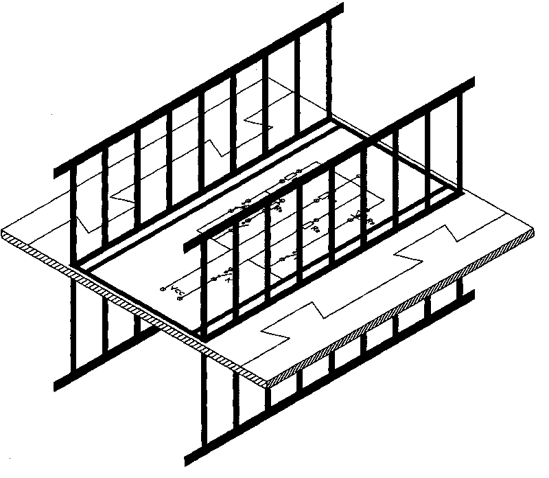
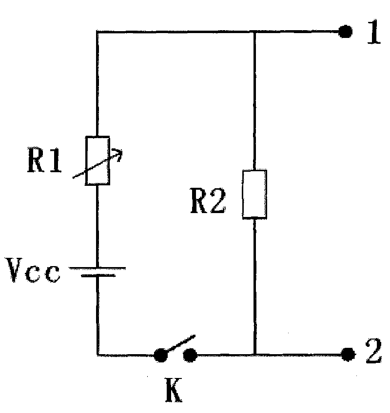
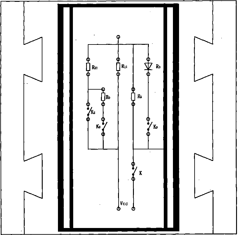
[0038] See attached Figure 1~3 As shown, test on a solar cell test device, the test process is as follows: figure 1 As shown, the test structure is placed between the probes of the solar cell test device, and the first test electrode 1 is in contact with the lower row of probes of the solar cell test device, and the second test electrode 2 is in contact with the upper row of probes. touch;

[0039] Then set the resistance of the rheostat module R1 of the test structure to be R11, test once with a solar cell test device, record the values ​​of relevant electrical performance parameters such as voltage V1 and current I1 obtained from the test; continuously measure 10 times, take the average value, and obtain V1 is 0.3644V, current I1 is 0.7010A;

[0040] Keep the device still, change the resistance of the rheostat module R1 of the test structure to R12, test it once with the solar cell test device, and record the values ​​of relevant electrical performance parameters such as ...

Embodiment 2

[0044] Test on a solar cell test device, the test process is as follows: the test structure is placed between the probes of the solar cell test device, and the first test electrode is in contact with the lower row of probes of the solar cell test device, the second The second test electrode is in contact with the upper row of probes;

[0045] Then set the resistance of the rheostat module R1 of the test structure to be R11, test once with a solar cell test device, record the values ​​of relevant electrical performance parameters such as voltage V1 and current I1 obtained from the test; continuously measure 10 times, take the average value, and obtain V1 is 0.3447V, current I1 is 0.6365A;

[0046] Keep the device still, change the resistance of the rheostat module R1 of the test structure to R12, test it once with the solar cell test device, and record the values ​​of relevant electrical performance parameters such as voltage V2 and current I2 obtained from the current test; co...


PUM


Abstract

The invention discloses a method and a device for detecting contact resistance of a probe, wherein the detection device comprises a variable-resistance module, a pressure dividing module, a first test electrode, a second test electrode, a power supply and a switch, wherein the variable-resistance module is connected with the pressure dividing module in series; the first test electrode and the second test electrode are connected to two ends of the pressure dividing module respectively; and the variable-resistance module has at least three variable resistance values. The method and device for detecting the contact resistance of the probe can correctly test the contact resistance of the probe for a test device so as to ensure measuring performance of the test device and to lay a basis for accurate test thereof.

Description

technical field [0001] The invention relates to a method for detecting contact resistance and a detection device thereof, in particular to a method for detecting contact resistance of a probe and a detection device thereof. Background technique [0002] In recent years, with the pollution of the earth's environment and the deterioration of the atmospheric environment, solar cells have entered the stage of history as a new type of pollution-free and renewable energy. At present, the main material widely used in the manufacture of solar cells is semiconductor silicon material, and its manufacturing process is also very mature. The general manufacturing process is: surface cleaning and structuring, diffusion, cleaning and etching to remove edges, anti-reflection coating, silk screen Printing sintering, testing. Among them, the main purpose of the test is to test the photoelectric conversion efficiency of solar cells. The main test items include electrical performance parameter...

Claims


Application Information

Patent Timeline
Patent Type & Authority Applications(China)
IPC IPC(8): G01R27/08
Inventor 章灵军王栩生房海冬
Owner CSI CELLS CO LTD
Learn More