
Method for modeling field-path cooperative model for predicting field line coupled system response

A system response and model building technology, applied in special data processing applications, instruments, electrical digital data processing, etc., to achieve the effect of simplifying analysis and simplifying difficulty

Active Publication Date: 2010-04-21
BEIHANG UNIV
View PDF0 Cites 15 Cited by
  • Summary
  • Abstract
  • Description
  • Claims
  • Application Information

AI Technical Summary

Problems solved by technology

The common defect of these three models is that because the model is described by the incident wave components, prior knowledge of the incident wave information is required, so most of the existing research is on ultra-broadband electromagnetic pulses, fast frontier electromagnetic pulses or nuclear electromagnetic pulses. Qualitative analysis with known forms of electromagnetic waves cannot establish a complete model from the interference source to the disturbed device

Method used


Image

  • Method for modeling field-path cooperative model for predicting field line coupled system response
  • Method for modeling field-path cooperative model for predicting field line coupled system response
  • Method for modeling field-path cooperative model for predicting field line coupled system response

Examples


Embodiment 1

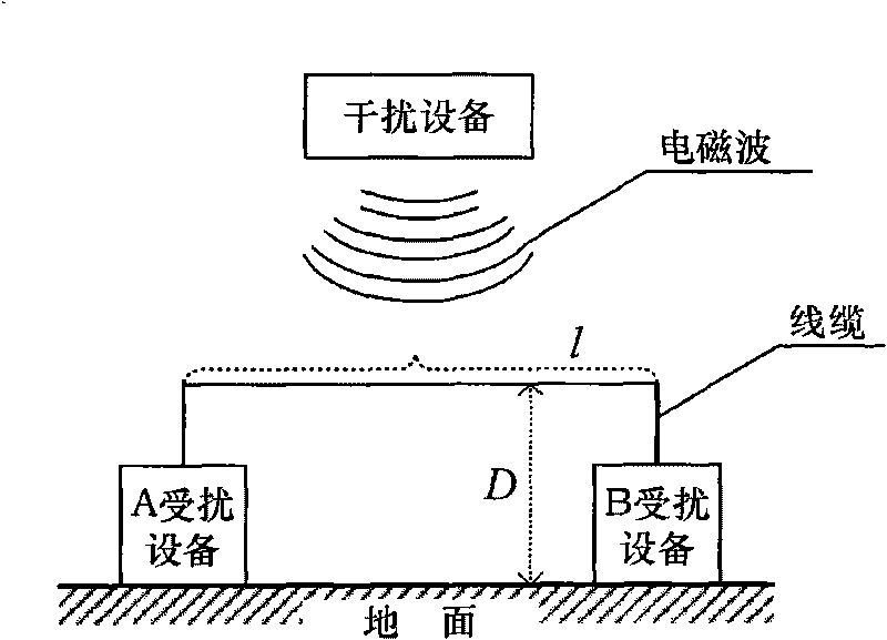
[0068] see Figure 5 As shown, the cable is connected between the disturbed device A and the disturbed device B, and the cable is subjected to the electromagnetic interference of the disturbing device A and the disturbing device B, and the cable coupling response detection is as follows:

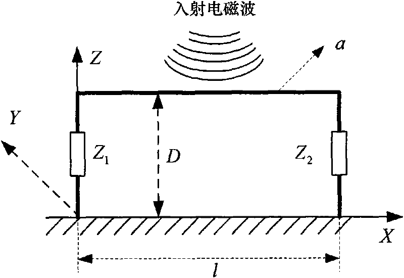
[0069] Cable parameters: l=1m, d=0.01m, a=0.0015m, Z 1 = Z 2 = 300Ω.

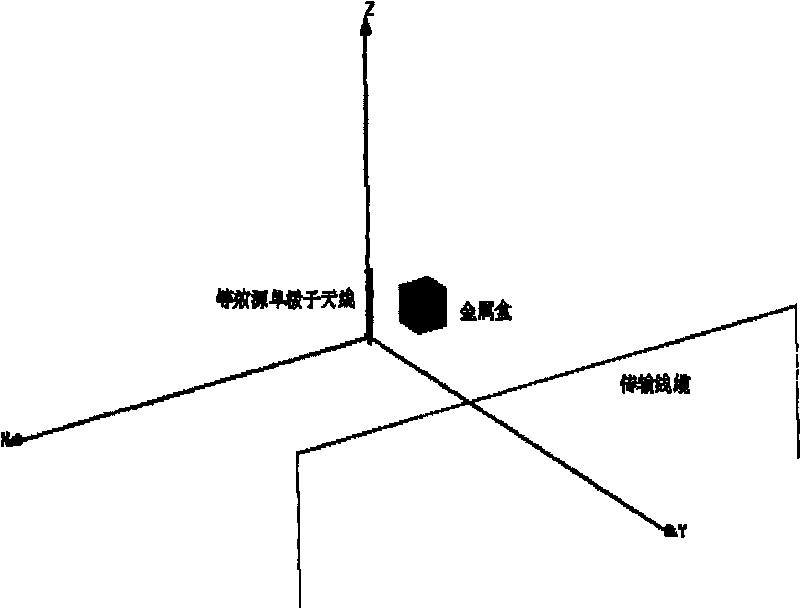
[0070] A behavior-level model of a jamming device such as Figure 5A As shown, the input signal is In 1 =0.07cos(2πft), transfer function where T N is a Chebyshev polynomial of order N. After the harmonic balance simulation of the ADS platform, the output signal is the excitation signal G of the radiation source equivalent to the A interference device. 1 (g 1 , φ 1 ).

[0071] The A jamming device is equivalent to the first cylindrical monopole antenna (see Figure 2A shown), its length LA 1 =1.077×10 -4 m, radius LR 1 =5×10 -6 m, excitation source voltage amplitude v 1 =3V, phase φ 1 =25°, simulation fr...

Embodiment 2

[0078] see Figure 5 As shown, the cable is connected between the disturbed device A and the disturbed device B, and the cable is subjected to the electromagnetic interference of the disturbing device A and the disturbing device B, and the cable coupling response detection is as follows:

[0079] Cable parameters: l=1m, d=0.01m, a=0.0015m, Z 1 = Z 2 = 300Ω.

[0080] The behavior-level models of the interference device A and the interference device B are the same as those in Embodiment 1, respectively.

[0081] The A jamming device is equivalent to the first rectangular monopole antenna (see Figure 2B shown), its length LA 1 =5×10 -6 m, width LB 1 =5×10 -6 m, high LC i =1.077×10 -4 m, excitation source voltage amplitude v 1 =3V, phase φ 1 =25°, simulation frequency f=696.5MHZ.

[0082] Equivalent the B jamming device to a second rectangular cylindrical monopole antenna (see Figure 2B shown), its length LA 2 =5×10 -6 m, width LB i =5×10 -6 m, high LC i =8.965...


PUM

PropertyMeasurementUnit
Dielectric constantaaaaaaaaaa

Abstract

The invention discloses a method for modeling a field-path cooperative model for predicting a field line coupled system response, which comprises the step of: using the combination of an ADS platform and an HFSS platform with a modified Taylor model under a single interference source radiation to create a complete model which couples electromagnetic wave radiated from jamming equipment to interfered equipment through a cable so as to obtain the responses of two pieces of terminal interfered equipment connected by the cable at the jamming equipment. In a state of a definite equivalent radiation source, the method for modeling a field-path cooperative model disclosed by the invention can be used for predicting a coupled response condition on the cable excited by the electromagnetic wave generated by any jamming equipment so as to provide information reference for device-level and system-level electromagnetic compatibility designs.

Description

technical field [0001] The present invention relates to a method for establishing a field-path coordination model, more particularly, it refers to a method for establishing a field-path coordination model for coupling responses generated by electromagnetic waves radiated by interference equipment to stimulate transmission cable terminal equipment, which belongs to electromagnetic compatibility technology interference Coupling forecasting and design domains. Background technique [0002] In electrical or electronic equipment, cables (cables or wires) are used to realize the connection between equipment and equipment, equipment and devices. When multiple devices work together, some devices will generate electromagnetic interference, which will be coupled to another device through cables, causing the performance of the other device to degrade or even fail to work normally. With the wide application of digital devices and integrated circuits, electronic devices are particularly...

Claims


Application Information

Patent Timeline
IPC IPC(8): G06F17/50
Inventor 陈文青汪玉梅吴龙刚苏东林
Owner BEIHANG UNIV
Learn More