
Fan mounted into a tube

A technology of fans and fan impellers, which is applied to parts of pumping devices for elastic fluids, pump devices, mechanical equipment, etc., can solve problems such as reducing fluid delivery efficiency, and achieve the effect of stabilizing flow loss

Inactive Publication Date: 2010-04-28
J·保韦蒂克
View PDF4 Cites 2 Cited by
  • Summary
  • Abstract
  • Description
  • Claims
  • Application Information

AI Technical Summary

Problems solved by technology

However, these filters reduce fluid transfer efficiency and must be replaced or cleaned frequently to maintain transfer efficiency at an acceptable level

Method used


Image

  • Fan mounted into a tube
  • Fan mounted into a tube
  • Fan mounted into a tube

Examples


Embodiment Construction

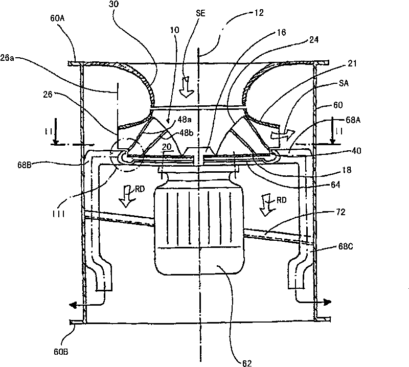
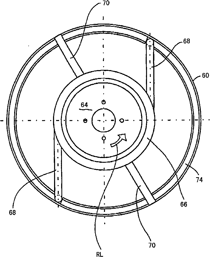
[0053] exist figure 1 The axis of the fan wheel arrangement installed in the pipe section 60 is designated with reference numeral 12 . The pipe section 60 is part of a pipe system for conveying a fluid or flow medium entrained with solid or liquid particles to be separated.

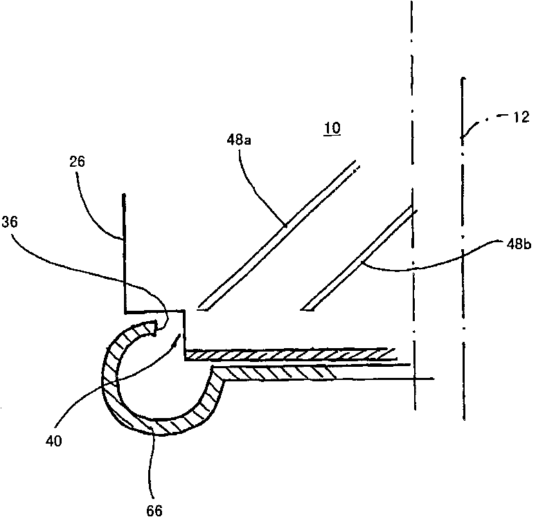
[0054] Specifically, an axial-inlet radial fan impeller is installed in the pipe section 60 , and the radial fan impeller is indicated by reference numeral 10 . The fan impeller should be capable of effectively conveying or pumping a gaseous flow medium entrained with abrasive particles (such as dust particles, water particles, snow flakes, fat particles and the like) from the surrounding environment. In addition, with figure 1 The fan wheel shown fulfills the task of largely separating the particles flowing past it. For this purpose, the following structure is provided:

[0055] The hub designated by reference numeral 16 is seated in a rotationally fixed manner on the drive shaft of a motor 62 , whic...


PUM


Abstract

The present invention relates to a device comprising a fan mounted in a tube, transferred in the axial direction, and driven by a motor. The fan is formed by an axial entry radial fan impeller comprising a driven bearing member, the bearing member extends basically vertical to a rotating axis and is provided with a blade device, and the fluid which enters basically along the axial direction turns outward along the radial direction by using the blade device. A discharging edge of the fan impeller blade locates on a pitch circle which is less than the inner diameter of the tube. The blades of the blade device are designed and / or oriented so that particles contained in a to-be-conveyed fluid are deflectable in a direction of a continuous gap in a preset axial extension between a bearing member and a collecting groove. The collecting groove is fixedly connected with a mounting plate for the motor, and a plurality of particle discharging pipes which are arranged in the circumferential direction and spaced apart from each other are tangentially led out from the collecting groove, and the dispcharging pipes are preferably fixed or welded on the inner wall of the pipes.

Description

technical field [0001] The invention relates to a motor-driven fan installed in a pipe and conveying in the axial direction. Background technique [0002] Fans of this type are known in various designs. However, such fans are generally formed as axial fans or axial fans, which suck in the fluid in the axial direction and convey it further in the axial direction. [0003] However, the medium that has to be conveyed in the pipe is often entrained with solid and / or liquid particles. The particles are, for example, fat particles, dust particles or snow or the like. If conventional fans are installed in such ducts, corresponding filters must be provided before or after the fan wheel in order to effectively separate these particles from the air flow. However, these filters reduce the fluid transfer efficiency and must be replaced or cleaned frequently to maintain the transfer efficiency at an acceptable level. Contents of the invention [0004] It is therefore the object of ...

Claims


Application Information

Patent Timeline
Patent Type & Authority Applications(China)
IPC IPC(8): F04D25/08F04D29/28
CPCF04D29/526F04D29/545F04D29/289F04D29/441
Inventor J·保韦蒂克
Owner J·保韦蒂克
Learn More