
Optical grating agglutination alignment mechanism in space heterodyne interferometer

A space heterodyne and interferometer technology, applied in the direction of optical devices, installation, optics, etc., can solve the problems of performance being easily affected by the environment, and the positioning accuracy of separated optical components is difficult to control, etc., to achieve simple structure, easy implementation, and convenient operation Effect

Inactive Publication Date: 2010-04-28
ANHUI INST OF OPTICS & FINE MECHANICS - CHINESE ACAD OF SCI
View PDF1 Cites 16 Cited by
  • Summary
  • Abstract
  • Description
  • Claims
  • Application Information

AI Technical Summary

Problems solved by technology

[0005] In order to solve the problem that the positioning accuracy of the separated optical elements of the existing spatial heterodyne interferometer is difficult to control, and the performance is easily affected by the environment, the present invention provides a spatial heterodyne interferometer that is easy to operate, highly reliable, and can monitor the interference effect in real time. The assembly and adjustment mechanism of grating bonding in the instrument

Method used


Image

  • Optical grating agglutination alignment mechanism in space heterodyne interferometer
  • Optical grating agglutination alignment mechanism in space heterodyne interferometer
  • Optical grating agglutination alignment mechanism in space heterodyne interferometer

Examples


Embodiment Construction

[0022] In the following, the present invention will be further described through embodiments with reference to the accompanying drawings.

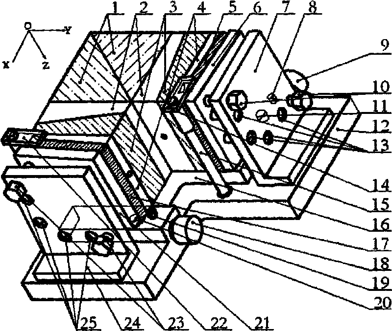
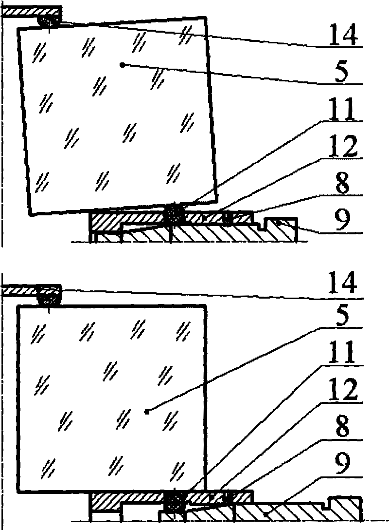
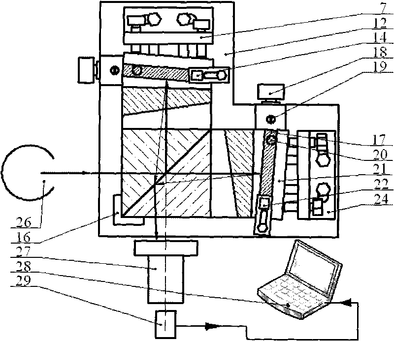
[0023] See figure 1 , figure 2 , On the interferometer substrate 16, the beam splitter 1, the wedge spacer 2, the field-expanding prism 3, and the grating spacer 4 arranged in two paths are formed in an "L" shape with two X arms and Y arms. The integrated interference body front unit at the end of the arm; in this embodiment, on the bottom plate 12, the two arm end positions of the integrated interference body front unit are respectively provided with an adjustment structure, and the adjustment structure is composed of a two-dimensional adjustment mechanism and an angle Adjust the structure of the organization;

[0024] Such as figure 1 As shown, in this embodiment, the two-dimensional adjustment mechanism provided at the end of the Y arm is composed of a fixed plate 7, an adjusting plate 6, a diagonal bolt 10, and a tension spring 13; wherein...


PUM


Abstract

The invention relates to an optical grating agglutination alignment mechanism in a space heterodyne interferometer, which is arranged on a base plate of the interferometer, comprises a beamsplitter, optical wedge distance pieces arranged in two paths, an expanding view field prism and an optical grating distance piece, takes on an 'L' shape and is an integrated interference body preposed unit provided with two arm ends which are an X arm and a Y arm. The mechanism is characterized in that a two dimension adjusting mechanism and an angular adjustment mechanism are respectively arranged at the two arm ends of the integrated interference body preposed unit on the base plate; meanwhile, a monitoring system formed by an even light source, an imaging lens positioned on an output optical axis, a CCD photoelectric receiving device and a display; and interference image is generated by the emergent ray of the even light source through the interferometer, and the monitor image can be acquired in the display. The mechanism is convenient for operation and strong in reliability, and can be used for monitoring the interference effect in real time.

Description

Technical field [0001] The invention relates to a grating gluing assembly and adjustment mechanism in a spatial heterodyne interferometer, in particular to a device capable of adjusting the relative inclination of the grating lines of two arms and a method for real-time detection of the effect of the adjustment image. Background technique [0002] The spatial heterodyne interferometer can obtain extremely high spectral resolution in a short spectral range. The system is equipped with four parts: front collimation system, interferometer system, imaging system and detector system; front collimation and imaging The lens barrel installation and positioning method of the system is very mature. Therefore, the difficulty of the system lies in accurately positioning the separate optical elements of the main body of the interferometer, the core component. [0003] The existing desktop optical system is built on an anti-seismic optical platform, and optical elements such as gratings, beam sp...

Claims


Application Information

Patent Timeline
IPC IPC(8): G02B7/00G01B9/02
Inventor 罗海燕熊伟施海亮李大成吴军方勇华
Owner ANHUI INST OF OPTICS & FINE MECHANICS - CHINESE ACAD OF SCI
Learn More