Light projection engine apparatus

A light projection and engine technology, applied in optics, photography, optical components, etc., can solve the problems of narrow light receiving angle, lighting light limitation, destruction, etc., and achieve the effect of improving light efficiency and improving utilization rate

Inactive Publication Date: 2010-05-05
XIAN ZHONGKE JINGXIANG PHOTOELECTRIC SCI & TECH
View PDF0 Cites 17 Cited by
  • Summary
  • Abstract
  • Description
  • Claims
  • Application Information

AI Technical Summary

Problems solved by technology

One of the most obvious drawbacks of the Cartesian light projection engine device 500 comprising only one PBS 200 and one modulating imager 110 is that only a limited portion of the illuminating light can reach the modulating imager 110 in one polarization state, so when After modulation and reflection by the modulation imager 110, the total illumination light projected onto the projection screen 390 through the projection lens system 300 is limited
In addition, the existing PBS200 is usually made of multilayer films or polymer materials containing organic substances, which are easily damaged by strong visible light or infrared radiation, and this multilayer film can be used for extremely oriented light receiving angle is very narrow

Method used


Image

  • Light projection engine apparatus
  • Light projection engine apparatus
  • Light projection engine apparatus

Examples


Embodiment Construction

[0021] In order to make the purpose, technical solutions and advantages of the embodiments of the present invention clearer, the technical solutions in the embodiments of the present invention will be clearly and completely described below in conjunction with the drawings in the embodiments of the present invention. Obviously, the described embodiments It is a part of embodiments of the present invention, but not all embodiments. Based on the embodiments of the present invention, all other embodiments obtained by persons of ordinary skill in the art without creative efforts fall within the protection scope of the present invention.

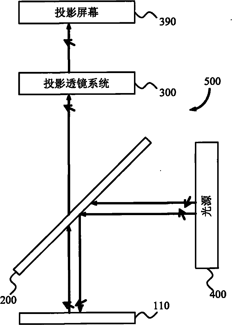
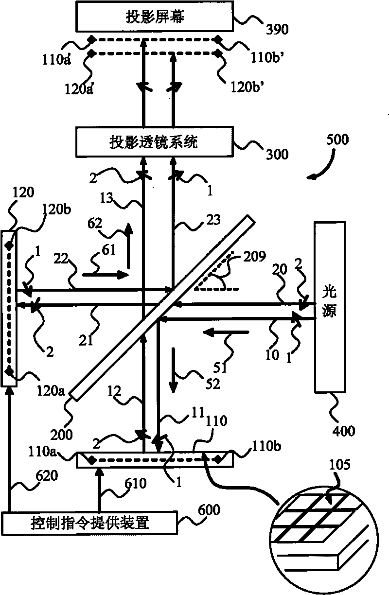
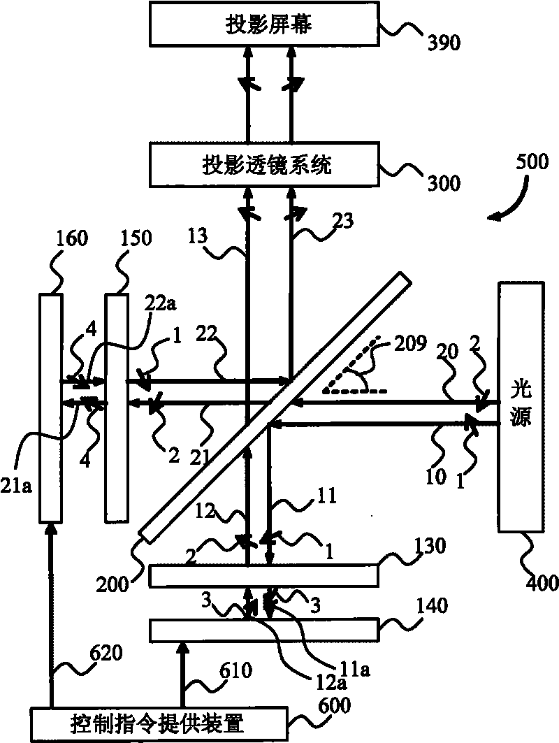
[0022] The various embodiments of the present invention can be applied to various micro-display projection systems, and in particular relate to a light projection engine device, using a PBS and a pair of polarization modulation imagers that are similar in structure but arranged symmetrically with the PBS, can improve light efficiency and three-dime...


PUM


Abstract

The inventive embodiment provides a light projection engine apparatus, including: a light source, PBS adopting symmetry lines grid, a first modulation imaging device, a second modulation imaging device, a projection lens system and a control command providing device. The inventive embodiment improves the light efficiency of modulation and image forming by improvements of use ratio of illumination light come form the polarization illumination light of the PBS.

Description

technical field [0001] The invention relates to a micro-display projection system, in particular to a light projection device using a reflective micro-display imager and a polarization beam splitter. Background technique [0002] Microdisplay projection systems typically employ transmissive or reflective microdisplay imagers, such as light valves or light valve arrays, to apply an image onto an illumination beam. The advantage of reflective light valves over transmissive light valves is that reflective light valves allow placement of control circuitry behind reflective surfaces, and since their opacity does not limit the substrate material, more advanced integrated circuit technologies can be applied. [0003] Reflective Liquid-Crystal-On-Silicon (LCOS) imager rotates the polarization direction of incident light, so that when the polarized light is reflected by the imager, its polarization state remains roughly unchanged or rotates a certain polarization angle to provide de...

Claims


Application Information

Patent Timeline
Patent Type & Authority Applications(China)
IPC IPC(8): G03B21/14G02B27/28G02B27/26G02F1/01G03B21/20G02B30/25
CPCH04N9/3167G03B21/14G02B27/26H04N13/0459H04N13/0427G02B5/3058G02B27/283G03B35/26H04N13/363H04N13/365G02B30/25
Inventor 唐德明
Owner XIAN ZHONGKE JINGXIANG PHOTOELECTRIC SCI & TECH
Why Eureka
Try Eureka