Stirring screw molding process and stripping back plate

A molding process and leaning technology, which is applied in the direction of manufacturing tools, casting molding equipment, casting molds, etc., can solve the problems of scrapped sand molds, poor control of strength, and sand mold distortion.

Inactive Publication Date: 2010-05-12
HENAN SIDA XIANLONG IND
View PDF0 Cites 0 Cited by
  • Summary
  • Abstract
  • Description
  • Claims
  • Application Information

AI Technical Summary

Problems solved by technology

Because the force cannot be well controlled when the sample mold of the mixing knife is rotated out, the molding sand will be compacted easily if the force is too large, which will cause the sand mold to be distorted; The molding yield is improved; and because the operation of this kind of mold removal process is difficult to control, the work efficiency is reduced

Method used


Image

  • Stirring screw molding process and stripping back plate
  • Stirring screw molding process and stripping back plate
  • Stirring screw molding process and stripping back plate

Examples


Embodiment Construction

[0018] The present invention will be further described below in conjunction with the accompanying drawings and embodiments.

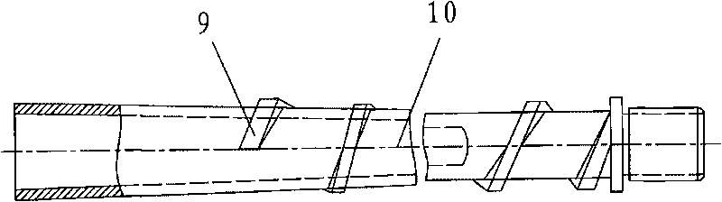
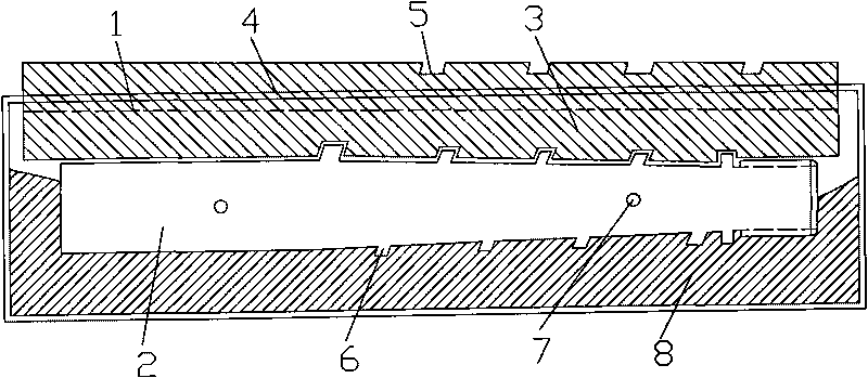
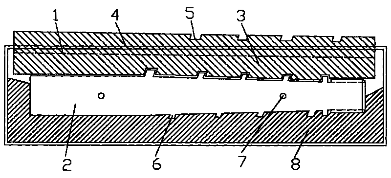
[0019] combine figure 1 with figure 2 Shown, during implementation, first make the mold-drawing backboard 1, the mold-drawing backboard 1 comprises the upper type backboard 4 and the lower type backboard 3, and the tooth form gap 5 of the lower type backboard 3 and the upper type backboard 4 is respectively connected with the The tooth types on both sides of the parting surface 2 of the mixing knife sample mold match. The plane formed by the axis 10; in the present embodiment, the lower type backing plate 3 and the upper type backing plate 4 are made on the same backing plate.

[0020] When making the mixer sand mold, use clay sand 8 to make the upper mixer mold and the lower mixer mold respectively. There is no sequence requirement for the production of the upper and lower mixer molds. For other craftsmen who make sand molds, they can refer to the t...


PUM


Abstract

The invention discloses a stirring screw molding process and a stripping back plate. The stripping back plate comprises an upper mold back plate and a lower mold back plate, wherein the tooth-shaped notches of the lower mold back plate and the upper mold back plate are matched with the tooth shapes on two sides of a parting surface of a stirring screw model; the parting surface of the stirring screw model is a plane formed by the tail end of the last tooth shape of the stirring screw model and the axis of the stirring screw; during stripping, the tooth-shaped notch of the upper mold back plate locks the tooth shape of an upper mold model, then pins are inserted in two plug pin holes of the upper mold model respectively, and the upper mold model is screwed out in a screw propelling direction by using the pins to obtain the upper mold of the stirring screw; in the same way, the lower mold of the stirring screw is formed; and finally, the upper and lower molds of the stirring screw are combined to obtain the stirring screw mold. The process avoids the distortion of a sand mold and improves the rate of finished stirring screw sand molds and the rate of finished stirring screw castings, thereby contributing to material conservation, cost reduction and production efficiency improvement.

Description

technical field [0001] The invention relates to the technical field of construction machinery and equipment manufacturing, in particular to a mixing blade molding process and a formwork lifting board. Background technique [0002] The mixing knife is a tool used to manufacture prestressed concrete round hole forming panels on the extruder. According to the function of different parts when the mixing knife is working, a mixing knife can be divided into three parts: thread connection section, screw propulsion section and round hole forming section. The spiral propulsion section of the mixing knife is composed of a spiral tooth type, and the tooth type itself spirals. The traditional method of removing the mixing knife is to loosen the mixing knife mold first, then insert two nails into the nail holes on the mixing knife mold, and then use the nails to unscrew the mixing knife sample mold. Because the force cannot be well controlled when the sample mold of the mixing knife is...

Claims


Application Information

Patent Timeline
Patent Type & Authority Applications(China)
IPC IPC(8): B22C9/00B22C19/06
Inventor 宋建恩宋向阳靳存文
Owner HENAN SIDA XIANLONG IND
Why Eureka
Try Eureka