Numerical control lathe for automatically machining cylindrical roller for bearing

A cylindrical roller and automatic processing technology, applied in the field of lathes, can solve the problems of low service life of lathes, easy wear of multiple parts, slow motor speed, etc., and achieve the effects of small frictional impact, small falling space, and increased processing efficiency

Active Publication Date: 2010-05-12
KEDE NUMERICAL CONTROL CO LTD
View PDF0 Cites 28 Cited by
  • Summary
  • Abstract
  • Description
  • Claims
  • Application Information

AI Technical Summary

Problems solved by technology

Solve the problems of slow motor speed, low processing efficiency, easy wear of multiple parts, and low service life of lathes of the same type in the prior art

Method used


Image

  • Numerical control lathe for automatically machining cylindrical roller for bearing
  • Numerical control lathe for automatically machining cylindrical roller for bearing
  • Numerical control lathe for automatically machining cylindrical roller for bearing

Examples


Embodiment Construction

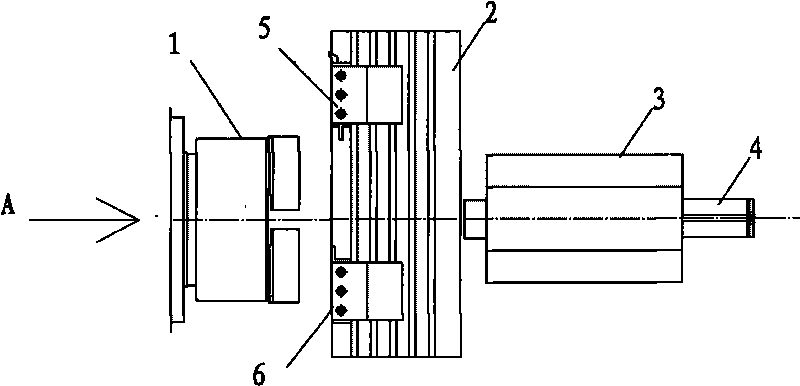
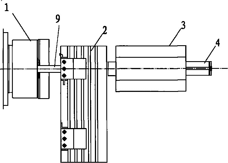
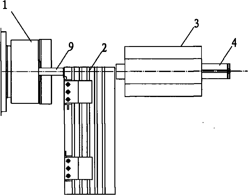
[0031] Such as Figure 9 As shown, the present invention is a numerically controlled lathe for automatically processing cylindrical rollers for bearings. The main body unit of the lathe includes a machine base 30, a workbench positioned on the machine base 30, a chuck assembly 14 for clamping a bar, and a driving chuck. The motor unit that the disc assembly 14 rotates, and the fixed cutter assembly ( Figure 9 not shown). In the figure, numeral 13 represents the position of the motor unit and its headstock. In the prior art, there is already a chuck assembly with a central hole passing through front and rear, and a drive motor thereof; the central hole is used as a space for conveying and clamping the bar. Thus as Figure 8 As shown, the bar is fed from the rear side A and sent to the right side of the chuck to facilitate the processing of the right tool.

[0032] In order to achieve the purpose of automatic production, the present invention sets a material holding unit, a ...


PUM

PropertyMeasurementUnit
diameteraaaaaaaaaa

Abstract

The invention discloses a numerical control lathe for automatically machining a cylindrical roller for a bearing, which comprises a lathe main body unit (2), wherein the lathe main body unit (2) comprises a chuck component used for clamping a bar, a motor unit driving the chuck component to rotate, and a cutter component realizing machining on a work bench, wherein 1 to 10 material holding units spaced in a straight line and a feed unit are arranged on the rear side of the chuck component; and a material receiving unit is arranged on the front side of the cutter component. The numerical control lathe can automatically complete bar machining, produces a semi-finished product and even a finished product of the cylindrical roller, is suitable for high-speed machining, and has the characteristics of low manpower cost, high production efficiency and high product quality.

Description

technical field [0001] The invention relates to a lathe, more specifically, relates to a lathe which continuously cuts bar stock and realizes rough machining of the bar stock at the same time to finally obtain cylindrical rollers. Background technique [0002] Under the existing technology, such as Figure 8 The lathe workbench shown for processing bars includes the bar clamp 1 on the left in the figure, and the clamp 2 for clamping tools on the right in the figure. A through hole is provided in the middle of the fixture 1 for the bar material to be fed from the rear side A and sent to the right side of the fixture 1 to realize the processing of the tools 5 and 6 on the right side. This machining is often used to form cylindrical rollers in bearing equipment. [0003] Based on the field of bearings, the roller bearing equipment produced by the original bearing manufacturer is a mechanical automatic lathe (cam lathe for short), which is mainly used for turning the rollers in...

Claims


Application Information

Patent Timeline
Patent Type & Authority Applications(China)
IPC IPC(8): B23B7/12B23B15/00B23B5/14B23B7/14B25B11/00
Inventor 于德海冯金龙邹弢刘翠山郭万甲鲍文禄李经明生财有周国峰
Owner KEDE NUMERICAL CONTROL CO LTD
Why Eureka
Try Eureka