
Processing method of engine connecting rod

A technology of an engine connecting rod and a processing method, which is applied in the field of engine connecting rods, can solve problems such as difficulty in guaranteeing processing accuracy, complex processing procedures, and heavy loads, achieve positioning accuracy and improve assembly quality, reduce processing accuracy and processing costs, The effect of improving productivity

Active Publication Date: 2010-05-12
CHERY AUTOMOBILE CO LTD
View PDF0 Cites 20 Cited by
  • Summary
  • Abstract
  • Description
  • Claims
  • Application Information

AI Technical Summary

Problems solved by technology

This kind of machining process is complex, costly, low in efficiency, and difficult to guarantee machining accuracy. If the rigidity of the connecting rod is not enough, the big head hole will be out of round and cause the big head bearing bush of the connecting rod to be burned due to oil film damage: the connecting rod shaft is bent, causing Piston and cylinder eccentric wear, piston ring air leakage and oil blow-by, etc.
At the same time, because the big end of the connecting rod of a heavy-duty diesel engine bears a large load, the roughness and cylindricity of the inner surface of the big end hole are very high, and the tool marks on the inner surface of the big end hole during boring are also easy to cause the connecting rod bearing to rotate in the big end hole. catastrophic damage to the engine

Method used


Image

  • Processing method of engine connecting rod
  • Processing method of engine connecting rod
  • Processing method of engine connecting rod

Examples


Embodiment Construction

[0021] Below with reference to the accompanying drawings, through the description of the embodiments, the specific embodiments of the present invention, such as the shape, structure, mutual position and connection relationship between the various parts, the role and working principle of the various parts, etc., will be further described. Detailed instructions:

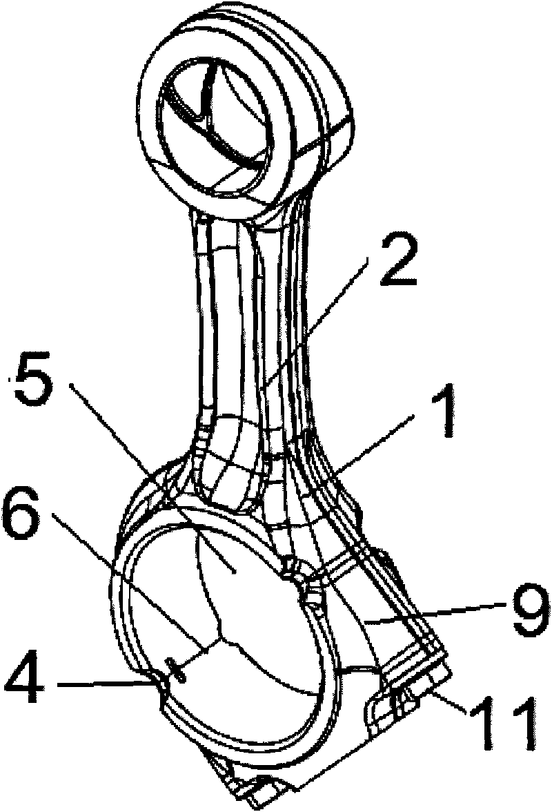
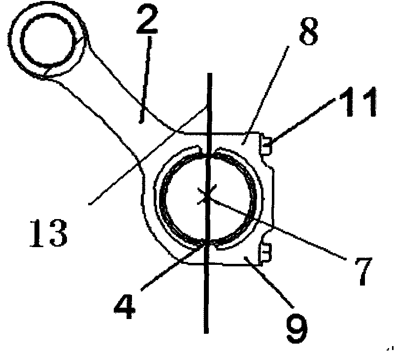
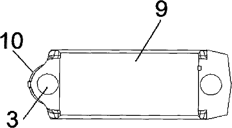
[0022] as attached figure 1 , 2 , 3, and 4, the present invention is a method for processing an engine connecting rod, and the main steps of the described method for processing an engine connecting rod are: a) processing a bolt on the fracture section 10 of the connecting rod blank 1 for fracture Connecting hole 3; b) then set a recessed pre-processed stress groove 4 at the edge of the connecting rod blank 1, and set a prefabricated crack groove 6 inside the connecting rod big hole 5 of the connecting rod blank 1; On the breaking processing equipment, the big end hole 5 of the connecting rod is applied to the big end...


PUM


Abstract

The invention provides a processing method of a connecting rod, applied in the field of an engine connecting rod. The processing method comprises the following steps: a) processing a bolt connecting hole (3) on a broken cross-section (10) of a connecting rod blank (1); b) arranging a preprocessing stress groove (4) on the edge of the connecting rod blank (1), and arranging a precrack groove (6) at the inner side of a connecting rod large-head hole (5); c) applying a cracking stress F (7) vertical to the predetermined broken section to the connecting rod large-head hole (5) on cracking processing equipment of the connecting rod; d) meshing a broken connecting rod body (2) and a connecting rod cover (9), penetrating with a bolt (11) and screwing tightly; and e) changing the finish-boring carried out in the connecting rod large-head hole (5) into a processing method of honing technique. The processing method greatly reduces the quantity of procedures, and improves the production efficiency; in addition, after the connecting rod body is separated from the rod cover, the separating surfaces of the rod and the cover can be meshed completely, and extra bolt positioning holes do not need to be added.

Description

technical field [0001] The invention relates to the field of an engine connecting rod, more specifically, relates to a processing method of an engine connecting rod. Background technique [0002] The function of the connecting rod is to transmit the force borne by the piston to the crankshaft, so that the reciprocating motion of the piston is converted into the rotational motion of the crankshaft. In the process of transmitting force, the connecting rod bears high periodic impact force, inertial force and bending force. This requires that the connecting rod should have high strength, toughness and fatigue performance. At the same time, because it is an important moving part of the engine, it requires high weight accuracy. With the development of the automobile industry, the manufacturing process of the connecting rod is also continuously improved. The main process of the traditional mechanical processing method is to rough mill the forging blank first, grind the two sides...

Claims


Application Information

Patent Timeline
Patent Type & Authority Applications(China)
IPC IPC(8): B23P15/00
Inventor 卢艳坤李为松胡文青李达成
Owner CHERY AUTOMOBILE CO LTD
Learn More