Breeches pipe arrangement method in arrangement of high-lift lock unilateral lock wall main corridor

A high-head, fork-pipe technology, applied in ship locks, ship lifting devices, climate change adaptation, etc., can solve problems such as affecting the stability of the fork-pipe structure, affecting the layout of energy dissipation facilities, and affecting the berthing conditions of the lock chamber, so as to improve engineering safety. The effect of high stability, low construction difficulty and simple structure

Active Publication Date: 2011-03-16
NANJING HYDRAULIC RES INST THE MINISTRY OF WATER RESOURCES THE MINIST
View PDF0 Cites 0 Cited by
  • Summary
  • Abstract
  • Description
  • Claims
  • Application Information

AI Technical Summary

Problems solved by technology

[0004] When the ship lock discharges water, the water flows into the valve through the fork pipe, the flow state of the water in the pipe directly affects the structural stability of the fork pipe itself, and the water flow condition at the outlet of the fork pipe directly affects the flow condition of the valve, which in turn affects the cavitation of the valve
When the ship lock is filled with water, the branch pipe is connected with the two upstream valves, and the water flows into the lock chamber after passing through the two valves and converging in the fork pipe. Therefore, the flow state of the confluence not only directly affects the berthing conditions of the lock chamber, but also affects the entrance and exit of the lock chamber. The layout of the energy dissipation facilities at the water outlet; and it takes a certain distance for the water to flow through the valve to restore stability, but engineering practice is often limited by space conditions, which makes the flow conditions of the fork pipe poor, so its own hydraulic problems and structural stability problems particularly prominent

Method used


Image

  • Breeches pipe arrangement method in arrangement of high-lift lock unilateral lock wall main corridor
  • Breeches pipe arrangement method in arrangement of high-lift lock unilateral lock wall main corridor
  • Breeches pipe arrangement method in arrangement of high-lift lock unilateral lock wall main corridor

Examples


Embodiment 1

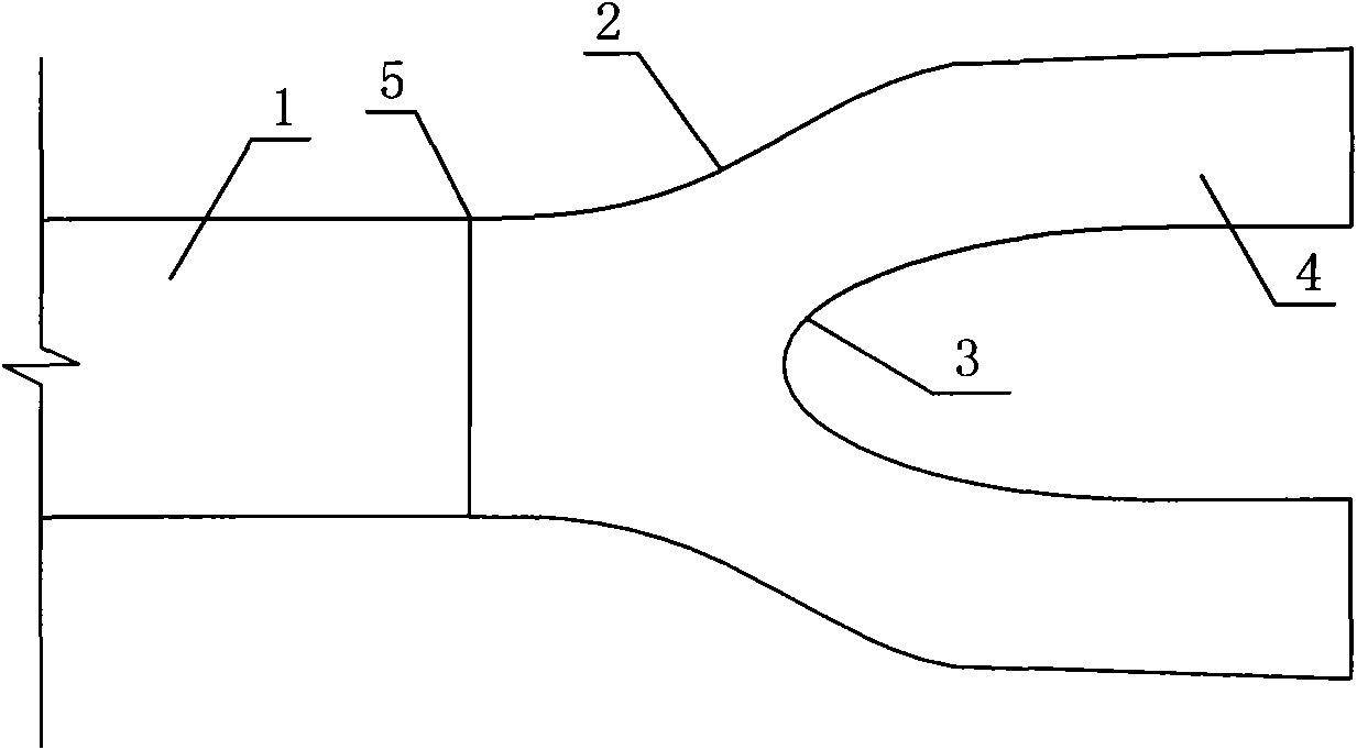
[0019] The arrangement of the present invention is as figure 1 As shown, a fork pipe arrangement form under the main corridor layout of the single-side lock wall of a high-head ship lock, at the entrance (distributor) of the fork pipe, the side wall curve 2 of the fork pipe is tangent to the main corridor 1, and tangent to At point 5, the curve 2 of the side wall of the fork pipe is streamlined; the end of the diversion pier 3 of the fork pipe is tangent to the wall 4 of the branch pipe, and the curve of the diversion pier 3 of the fork pipe is elliptical.

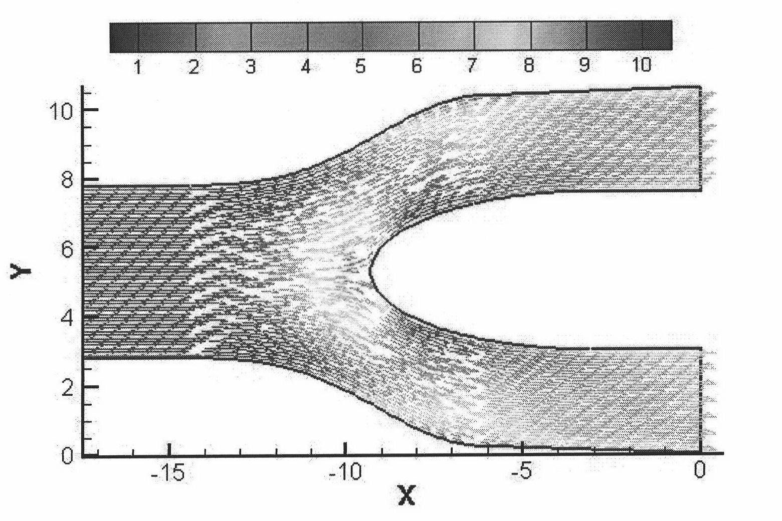
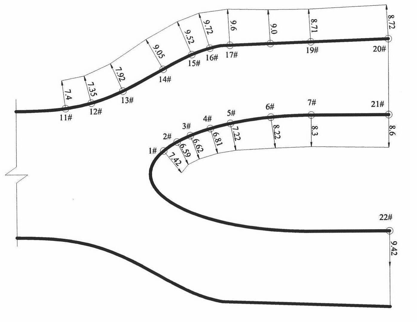
[0020] figure 2 , image 3 and Figure 4 It is the flow field in the pipe and its pipe wall pressure distribution diagram (both sides operation) of the present invention. Figure 5 , Figure 6 and Figure 7 It is the flow field in the pipe and its pipe wall pressure distribution diagram (bilateral operation) of the present invention.

[0021] image 3 , Figure 4 , Figure 6 , Figure 7 The time-average pressure...


PUM


Abstract

The invention relates to a lock water delivery system corridor form, in particular to a breeches pipe arrangement method in the arrangement of a high-lift lock unilateral lock wall main corridor, comprising a main corridor, a breeches pipe side wall, a branch pipe and a diversion pier, wherein an inlet and an outlet of the breeches pipe both have rectangular cross sections, a breeches pipe side wall curve is tangent with the main corridor at the inlet of the breeches pipe (a diversion gap), and the breeches pipe side wall curve adopts stream line form; and the tail end of the breeches pipe diversion pier is tangent with the branch pipe wall, and the breeches pipe diversion pier curve adopts elliptic type. In the invention, water flow in the pipe has smooth transition, and forms wall pressing flow, thus being beneficial to the stability of the breeches pipe, the state of flow at the outlet of the breeches pipe, and the diversion of the breeches pipe; and the water flow is not separatedfrom the pipe wall after diversion, the water flow in the pipe is smooth with less turbulence, flow bias does not occur in the pipe, and the pressure distribution at the outlet is uniform, thus effectively reducing the horizontal and longitudinal distance between the breeches pipe and a connecting section of a valve, and effectively solving the problem of incoming flow at the inlet of the valve.

Description

technical field [0001] The invention relates to a body shape of a water delivery corridor of a ship lock water delivery system, in particular to a fork tube arrangement form under the arrangement of the main corridor of a single side lock wall of a high water head ship lock. Background technique [0002] The ship lock water delivery system is an important part of the ship lock. Its development has gone through hundreds of years, and the initial water delivery system was very simple. Since the 1950s, the development of the water delivery system has entered a new stage. The constant inertia water delivery system that can adapt to large ship locks with high water heads has been developed, and the theory of hydraulic calculation of ship locks has also become more mature. [0003] In order to make the water flow in the lock chamber evenly distributed, the ship lock generally adopts the main corridor layout of the double-sided lock wall. When the landform and geological conditions...

Claims


Application Information

Patent Timeline
Patent Type & Authority Patents(China)
IPC IPC(8): E02C1/06
CPCY02A10/30
Inventor 胡亚安严秀俊张志崇李中华李君
Owner NANJING HYDRAULIC RES INST THE MINISTRY OF WATER RESOURCES THE MINIST
Why Eureka
Try Eureka