Bowl type turbulence-inhibiting flow-stabilizing flow distribution device for continuous casting of thin band

A diverting device and bowl-type technology, applied in the field of molten steel steady flow distribution and pouring device, can solve the problems of molten pool liquid level fluctuation, uneven flow distribution, and uneven molten pool temperature, so as to improve the distribution, ensure normal operation, Avoid the effect of volatility

Inactive Publication Date: 2010-05-19
SHANGHAI UNIV
View PDF6 Cites 7 Cited by
  • Summary
  • Abstract
  • Description
  • Claims
  • Application Information

AI Technical Summary

Problems solved by technology

[0003] In the past, the problem of the traditional thin strip pouring nozzle or flow distributor is mainly that there is no internal device to suppress or reduce the turbulent flow and the impact force of the stream during the flow of molten steel, which leads to unstable flow of molten steel, which in turn causes Fluctuation of the liquid lev

Method used


Image

  • Bowl type turbulence-inhibiting flow-stabilizing flow distribution device for continuous casting of thin band
  • Bowl type turbulence-inhibiting flow-stabilizing flow distribution device for continuous casting of thin band
  • Bowl type turbulence-inhibiting flow-stabilizing flow distribution device for continuous casting of thin band

Examples


Embodiment 1

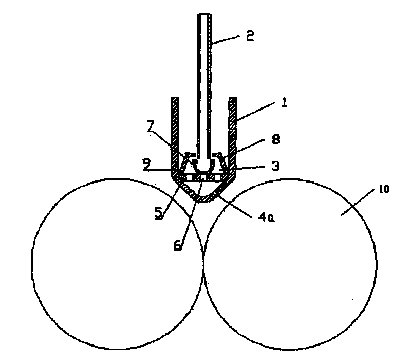
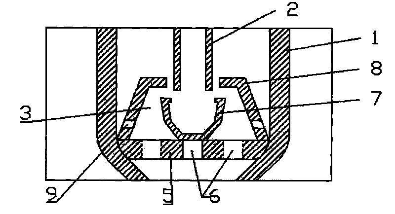
[0023] Embodiment one: see figure 1 , figure 2 , image 3 and Figure 4 , the thin strip continuous casting bowl-type turbulence suppression and steady flow distribution device includes a flow distributor 1 arranged above the rotating roller 10 and a pouring nozzle 2 extending into the cavity of the flow distributor 1, and the flow distributor 1 is "V" type Cavity structure, the upper part is an open rectangular cavity, the lower part is a narrow and long groove cavity with a "V" shape in cross section, and the lower bottom transitions with a circular arc. Orifice 4a; in the "V"-shaped long and narrow groove cavity, above the distribution flow hole 4a, there is a horizontally arranged orifice plate 5 covering the "V"-shaped long and narrow groove cavity, the orifice plate 5 1-3 rows of small holes 6 are evenly distributed along the direction of the roller axis; a bowl-type turbulence suppression and diversion device 3 is installed at the center of the orifice plate 5 . Th...

Embodiment 2

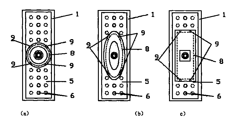
[0024] Embodiment two: see image 3 (a) Figure, the present embodiment is the same as Embodiment 1, and the special feature is that the upper and lower ends of the outer bowl 8 are circular, and there is a smooth transition between the upper and lower ends.

Embodiment 3

[0025] Embodiment three: see image 3 (b) Figure, the present embodiment is the same as the first embodiment, and the special feature is that the upper and lower ends of the outer bowl 8 are elliptical, and there is a smooth transition between the upper and lower ends.


PUM


Abstract

The invention relates to a bowl type turbulence-inhibiting flow-stabilizing flow distribution device for the continuous casting of a thin band, comprising a flow distributor and a casting water gap, wherein the flow distributor is arranged above a roller and in a V-shaped cavity structure; the casting water gap extends into a cavity of the flow distributor; the upper part of the flow distributor is provided with an opened rectangular cavity, the lower part of the flow distributor is a long and narrow slot cavity with a V-shaped section, and the bottom of the flow distributor is transited with an arc; the two skew walls of the slot cavity are provided with a plurality of flow distribution holes near the bottom of the slot cavity; a horizontal arranged hole plate positioned in the V-shaped long and narrow slot cavity and above the flow distribution holes covers the V-shaped long and narrow slot cavity; one to three rows of small holes are uniformly distributed on the hole plate along a roll shaft direction; a bowl type turbulence-inhibiting flow-dividing device is arranged in the center of the hole plate. The invention obviously improves the distribution of liquid steel in a molten pool, promotes the liquid steel to stably flow and inhibits the influence of the impact of casting flows so that the flow of the liquid steel is more reasonable and the temperature distribution is more uniform, thereby enhancing the casting quality of the thin band.

Description

technical field [0001] The patent of the invention relates to a liquid steel steady flow distribution pouring device used in the thin strip continuous casting production process, which belongs to the technical field of thin strip continuous casting. Background technique [0002] In thin strip continuous casting production, the reasonable distribution and distribution of molten steel in the molten pool has a very important impact on the final strip quality, so the thin strip continuous casting distribution device plays a very important role in the entire thin strip production. Various countries have launched a lot of research in this regard, such as the disclosed dispensers of US Pat. The molten steel flowing in from the tundish flows into the flow distributor through a row of flow holes in the distributor. The flow distributor described in Chinese patents ZL01276402.7 and ZL02283420.6 is an integral hoisting device, and the flow distribution is achieved through the distribu...

Claims


Application Information

Patent Timeline
IPC IPC(8): B22D11/06B22D11/103
Inventor 杨帆王波刘恭源张捷宇许继芳齐建波张立吴广新揭畅张纬栋
Owner SHANGHAI UNIV
Why Eureka
Try Eureka