
Quantitative filling device for filing machine

A filling device and filling machine technology, applied in packaging, bottle filling, liquid bottling, etc., can solve problems such as high failure rate, changeable flow path bending, and slow filling speed

Inactive Publication Date: 2010-05-19
刘耀宇
View PDF0 Cites 24 Cited by
  • Summary
  • Abstract
  • Description
  • Claims
  • Application Information

AI Technical Summary

Problems solved by technology

This method has a large range of capacity adjustment, and the efficiency is slightly higher when it is roughly adjusted in a large range. However, for each filling valve, it must be manually fine-tuned by the fine-tuning device after rough adjustment, and it must be measured and adjusted several times to reach the capacity. Accuracy requirements
Compared with the first type of filling valve, the improvement of the second type of filling valve is that the range of capacity adjustment is obviously enlarged, and the way of capacity adjustment is slightly convenient, but it is still not ideal.
[0005] The common disadvantages of the two are: the internal structure is complex, the failure rate is high; the flow path is curved and changeable, and the filling speed is slow; the filling valve is non-terminal closed, and there is residual leakage on the wall.

Method used


Image

  • Quantitative filling device for filing machine
  • Quantitative filling device for filing machine
  • Quantitative filling device for filing machine

Examples


Embodiment Construction

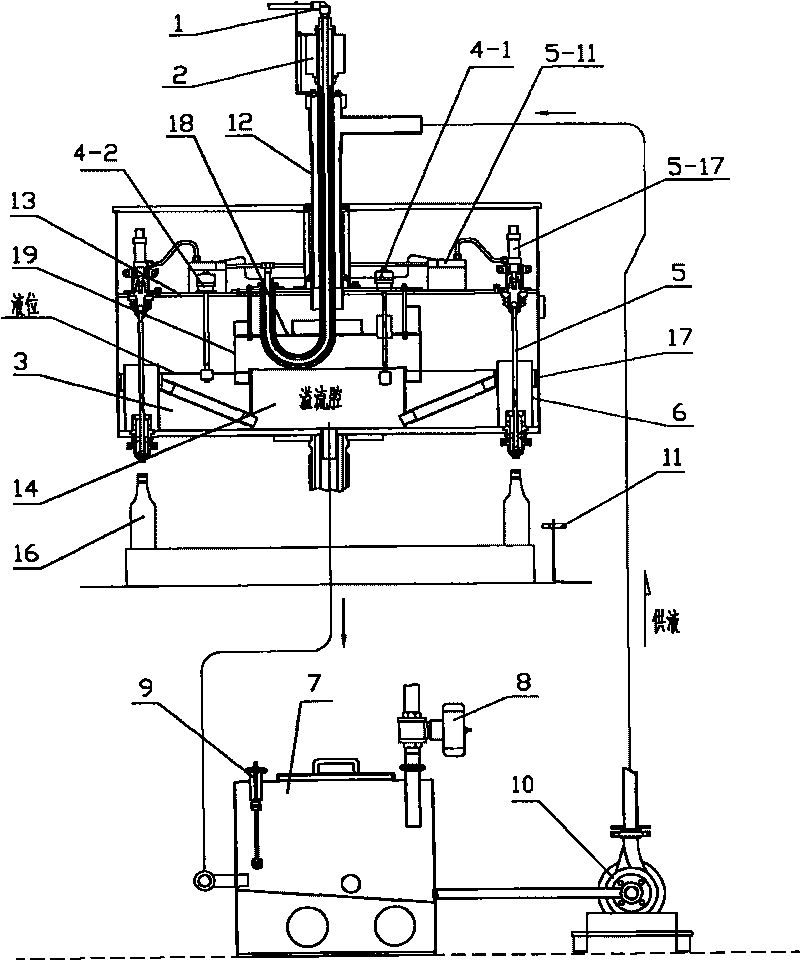
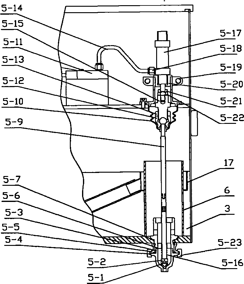
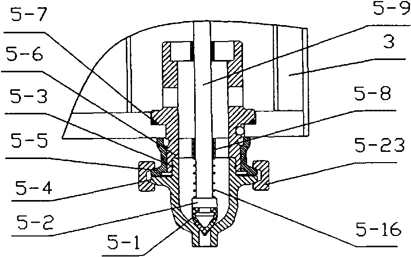
[0019] Referring to the accompanying drawings, the quantitative filling device used in the filling machine is to install a rotary liquid cylinder 3 on the top of the filling machine. The filling machine is equipped with a PLC controller (filling machine control system), and in the rotary liquid cylinder 3 A filling valve 5 is installed, and a liquid nozzle is installed at the lower part of the filling valve 5. A scanning sensor 11 is installed on the filling machine corresponding to the liquid nozzle, and the scanning sensor 11 is fixed behind the bottle-feeding wheel. Under the action of the bottle-feeding wheel, the bottle-feeding chain enters the turntable of the main machine, and when it rotates around the center of the main machine with the turntable, it passes through the front end of the scanning sensor, and the scanning sensor sends a signal to the PLC controller, and then the PLC sends an instruction to open the filling valve, filling starts. On one side of the fillin...


PUM


Abstract

The invention discloses a quantitative filling device for a filing machine, which comprises a rotary liquid tank which is arranged on the filing machine, wherein a PLC controller is arranged on the filing machine; a horizontal clapboard is arranged on the middle part of the rotary liquid tank; a filing valve passing through the middle part and the bottom part of the rotary liquid tank is arranged around the rotary liquid tank; a liquid outlet nozzle is arranged on the lower part of the filing valve; a scanning sensor is arranged on the part of the filing machine, which corresponds to the liquid outlet nozzle; an air cylinder used for driving the filing valve to open and close is arranged on the horizontal clapboard; a solenoid valve used for controlling the opening and closing of the air cylinder is arranged on an air supply pipeline of the air cylinder; a buffer tank used for supplying liquid to the rotary liquid tank is independently arranged on one side of the filing machine; and the scanning sensor and the solenoid valve are controlled by the PLC controller. In the invention, the filing capacity is controlled by controlling a filing time, the capacity can be adjusted steplessly and conveniently in a large range, and the volume fixing accuracy is high; and the internal structure of the filing value is simple, the liquid flow resistance is small, the filing speed is high, and the filing valve adopting terminal opening and closing has no leakage and residual drip.

Description

technical field [0001] The invention relates to a liquid quantitative filling device for injecting liquid into containers such as bottles. Background technique [0002] At present, in liquid constant volume filling machines, the common way of volume adjustment is mechanical volume adjustment, and there are two main forms: [0003] (1) Single-capacity quantitative filling valve (or double-capacity quantitative filling valve), the measuring cup of the filling valve is placed at the bottom of the liquid cylinder (outside the liquid cylinder), the measuring cup is connected to the liquid cylinder, and the side of the measuring cup is equipped with a volume adjustment device, which is manually operated To adjust the capacity, use a special wrench to turn the volume-adjusting piston to make it move inward or outward, so as to change the volume inside the measuring cup, so as to achieve the purpose of volume adjustment. According to the number of adjustable volume sections, it is ...

Claims


Application Information

Patent Timeline
IPC IPC(8): B67C3/26
Inventor 刘耀宇崔金波
Owner 刘耀宇
Learn More