Phase shifter module based on medium loading

A medium loading and phase shifter technology, which is applied to waveguide devices, electrical components, circuits, etc., can solve the problem that the linear relationship between the phase shifter and the medium phase shifter cannot be guaranteed, it is difficult to ensure a good standing wave, and the layout flexibility is not enough. and other problems, to achieve the effect of flexible layout, low cost and small vertical size

Active Publication Date: 2010-05-19
TONGYU COMM INC
View PDF7 Cites 18 Cited by
  • Summary
  • Abstract
  • Description
  • Claims
  • Application Information

AI Technical Summary

Problems solved by technology

The phase shift amount can be changed by changing the insertion degree of the dielectric sheet, but the dielectric sheet design with a simple shape cannot guarantee the linear relationship between the phase shift amount and the medium phase shi

Method used


Image

  • Phase shifter module based on medium loading
  • Phase shifter module based on medium loading
  • Phase shifter module based on medium loading

Examples


Embodiment 1

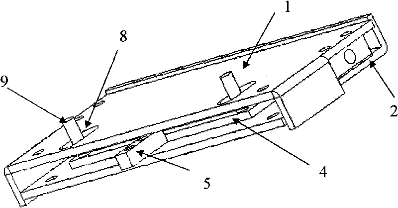
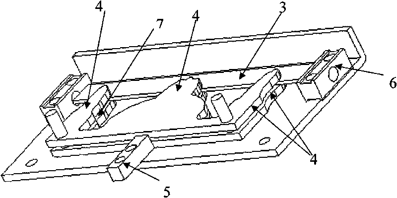
[0029] to combine figure 1 and figure 2 , In the specific embodiment of the present invention, a stripline structure is adopted, and the phase shifter module includes a stripline structure, three dielectric sheets 4 , a lever 5 for manipulating the movement of the dielectric sheet, and a cable welding seat 6 . The stripline structure includes an upper cover plate 1, a lower base plate 2 and a strip line 3; the strip line is located between the upper cover plate and the lower base plate, with air in between, forming an air strip line; the dielectric sheet 4 has a gap 6 , to ensure that the dielectric sheet 4 is in close contact with the strip line 3 when sliding. The dielectric sheet 4 is integrally formed or connected by plastic structural parts. The dielectric sheet in the middle has a larger area, and the dielectric sheets on both sides have a smaller area. The area of ​​each dielectric sheet changes stepwise along the running direction and is symmetrical from left to righ...

Embodiment 2

[0039] The above scheme is applicable to the microstrip line structure. Since the microstrip line structure does not have an upper cover plate, the difference from Embodiment 1 is that the chute, which is one of the components of the limiting device, is opened on the lower bottom plate for the guide provided on the dielectric sheet. The column is inserted; the dielectric sheet can be selected without opening a gap, and is directly located between the microstrip line and the lower bottom plate.


PUM


Abstract

The invention relates to the field of mobile communication base station antennae, in particular to a phase shifter applied to electric tilt base station antennae. The invention discloses a phase shifter module based on medium loading, comprising a transmission line structure which takes air as transmission medium and a basic transmission mode as a TEM model or a quasi-TEM model, such as strip lines or microstrip lines. The phase shifter module is characterized in that the phase shifter module also comprises at least one movable medium sheet arranged between transmission lines; according to the strip line structure, the medium sheet is also provided with a gap for arranging the strip line; along with the movement of the medium sheet, transmission lines and the medium sheet have relative displacement; and phase position delay is changed by changing the superposition area of the medium sheet and the transmission lines so as to realize signal phase shift. When the phase shifter works, the medium sheet moves vertically to energy transmission direction; by selecting medium material with low loss, the phase shift module has the advantages of low insertion loss, less spurious radiation, large phase shift amount, small volume, low cost and the like, and the phase shift amount and the medium sheet displacement are in linear relation; because of adopting modular design, the invention can be conveniently connected via the coaxial line, thus realizing flexible layout and diversified phase shift and feed network design.

Description

Technical field: [0001] The invention relates to the field of mobile communication base station antennas, in particular to a phase shifter module applied to base station electric adjustment antennas. Background technique: [0002] The phase shifter is the core component of the electric antenna of the base station. The current design of the phase shifter generally adopts the following two methods: 1. Change the electrical length of the signal passing path in the phase shifter. The continuously variable phase shifters described in patent documents with patent No. ZL200520065549.5 and patent No. ZL 200520121325.1 all change the electrical length of the passing path by changing the relative contact length of the copper (aluminum) sleeve . In order to reduce sliding resistance and ensure low passive intermodulation products in this method, it is often necessary to transmit signal energy through coupling. The length of the sleeve of the coupling section should generally not be to...

Claims


Application Information

Patent Timeline
IPC IPC(8): H01P1/18H01Q3/30
Inventor 伍裕江付香芽高卓锋陈鹏吴中振叶海鸥陈益凯
Owner TONGYU COMM INC
Why Eureka
Try Eureka