Electrode leading structure and electricity storage electric element adopting thereof

A lead-out structure and electrode lead-out technology, applied in the direction of electrical components, structural parts, capacitor parts, etc., can solve the problems of limited mechanical strength, high processing precision, loose end caps, etc., and achieve saving sealing insulation materials and low processing accuracy requirements , the effect of increasing the connection strength

Active Publication Date: 2010-05-26
ZHENGZHOU SINO CRYSTAL DIAMOND
View PDF0 Cites 10 Cited by
  • Summary
  • Abstract
  • Description
  • Claims
  • Application Information

AI Technical Summary

Problems solved by technology

The electrode lead-out structure using the above structure has the following problems: the sealing structure is complex, especially the concave structure at the top end of the shell and the groove on the upper surface around the end cover require high machining accuracy, and the cost of manufacturing and assembly is high; The insulating sleeve and the sealing ring are set independently, and the assembly is complicated and cumbersome. Failure of any one will cause damage to the battery or supercapacitor; During the use of the capacitor, its peripheral parts are easily deformed by bumps, resulting in the leakage of the electrolyte inside the battery or supercapacitor or the short circuit of the positive and negative electrodes, resulting in damage to the battery or supercapacitor
In addition, the mechanical strength of the casing of the battery or supercapacitor is limited, and its sealing effect is poor, and the end cap is easy to loosen in the casing

Method used


Image

  • Electrode leading structure and electricity storage electric element adopting thereof
  • Electrode leading structure and electricity storage electric element adopting thereof
  • Electrode leading structure and electricity storage electric element adopting thereof

Examples


Embodiment Construction

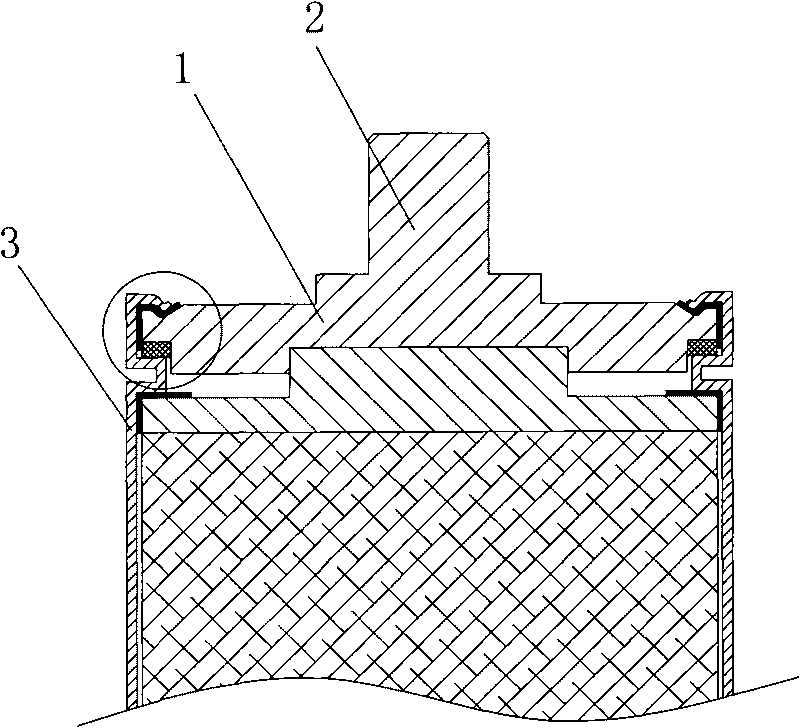
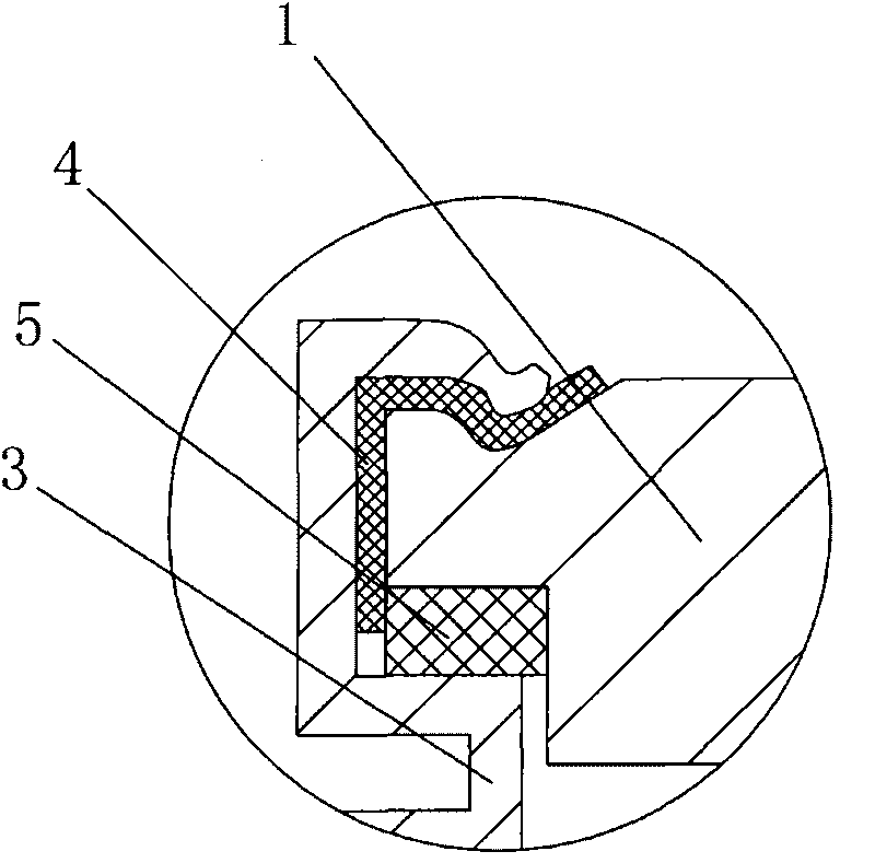
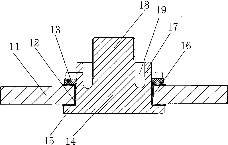
[0023] The electrode drawing structure of the present invention is as image 3 As shown, it includes an end cover 11 for sealing and fixing at the extreme opening of the battery or supercapacitor casing 21, and a lead-out hole 16 is opened in the center of the end cover 11, and a pole 14 is inserted in the lead-out hole 16. The bottom of 14 is provided with the retaining edge 15 that is used to prevent pole from falling off, and the top protrudes from the hole 16 aperture and is respectively provided with the pole lead-out 18 coaxial with the pole and the hollow around the pole lead-out 18. The flanging structure is an axial groove 19 arranged on the top of the pole 14, the outer surface of the groove wall 17 is consistent with the shape of the outer peripheral surface of the pole, and the pole lead-out 18 is in line with the concave The inner side wall of the groove 19 is a gap fit, the bottom of the lead-out end 18 of the pole is fixedly connected to the bottom of the groove...


PUM


Abstract

The invention discloses an electrode leading structure of a battery or a super capacitor, which comprises an end cover. The end cover is hermetically fixed at the opening of the electrode end of a battery or capacitor outer casing. A terminal is inserted in the middle of the end cover, and the top end of the terminal extends out of the end cover. The bottom of the terminal is fixedly provided with a stop edge which is used for preventing the terminal from falling, and the top is respectively provided with a terminal leading end and a hollow flanging structure which is arranged around the terminal leading end. An insulation and sealing sleeve is clamped between the terminal and the end cover, and is sleeved on the terminal for sealing the terminal. The invention also discloses an electricity storage electric element which adopts the electrode leading structure. The electrode leading structure adopts a split structure of the terminal and the end cover; one insulation and sealing sleeve is used for sealing and insulating when the terminal is assembled; the flanging structure is sealed and compressed after being flanged; the sealing structure is simple, and is convenient and rapid in installation; and the sealing part is arranged around the terminal, so that the sealing and insulation material is saved.

Description

technical field [0001] The invention relates to an electrode lead-out structure, in particular to a battery or supercapacitor electrode lead-out structure, and also relates to a power storage electrical component adopting the lead-out structure. Background technique [0002] A battery or a supercapacitor is an electrical component with the function of storing electricity. Its electrode lead-out structure is an important part used to connect the internal pole core of the battery or supercapacitor and the power supply equipment. It is necessary to ensure that the two electrodes of the battery or supercapacitor Insulation between them, and at the same time ensure a good sealing effect on the electrolyte inside the battery or supercapacitor. At present, the electrode lead-out structure of commonly used batteries or supercapacitors is as follows: figure 1 , 2 As shown, it includes an end cover 1 for sealing and fixing on the battery or supercapacitor casing, and the top end of ...

Claims


Application Information

Patent Timeline
Patent Type & Authority Applications(China)
IPC IPC(8): H01M2/00H01M2/04H01M2/30H01M2/08H01M2/06H01M10/00H01M6/00H01G9/008H01G9/08H01M50/14H01M50/147H01M50/172H01M50/188
CPCY02E60/12Y02E60/13
Inventor 赵志伟库敬轩孙贯英张德林冯杰刘喜龙张红涛梁晓鸽
Owner ZHENGZHOU SINO CRYSTAL DIAMOND
Why Eureka
Try Eureka