
Fluorescent signal exciting and detecting device for postpositive imaging diaphragm plate

A technology for detecting devices and fluorescent signals, which is applied in measuring devices, fluorescence/phosphorescence, material excitation analysis, etc. It can solve problems such as system interference, high cost of lens systems, unfavorable system miniaturization, etc., to improve signal-to-noise ratio and avoid diffraction effect of effect

Inactive Publication Date: 2010-06-02
FUJIAN NORMAL UNIV
View PDF0 Cites 1 Cited by
  • Summary
  • Abstract
  • Description
  • Claims
  • Application Information

AI Technical Summary

Problems solved by technology

[0004] However, this approach also has many disadvantages
The method of using a lens system to shape the excitation beam into an oblong elliptical spot often uses a large lens system, which is not conducive to the miniaturization of the system, and the cost of the lens system is often high, and the adjustment and focus accuracy requirements are high, thereby increasing System design and manufacturing costs
It seems simple and easy to use a light block to block the excitation light into a strip-shaped spot. However, when the flow cytometry system detects micron-scale samples, the slit width of the light block must be smaller than the size of the sample. The existing processing technology of slit light block is difficult to manufacture. Even if a high price is paid to make a light block with a slit width of micron level, diffraction is prone to occur, and the fluorescence excited by different levels of diffracted light bands will cause great damage to the system. interference

Method used


Image

  • Fluorescent signal exciting and detecting device for postpositive imaging diaphragm plate
  • Fluorescent signal exciting and detecting device for postpositive imaging diaphragm plate

Examples


Embodiment Construction

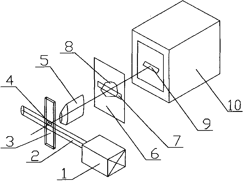
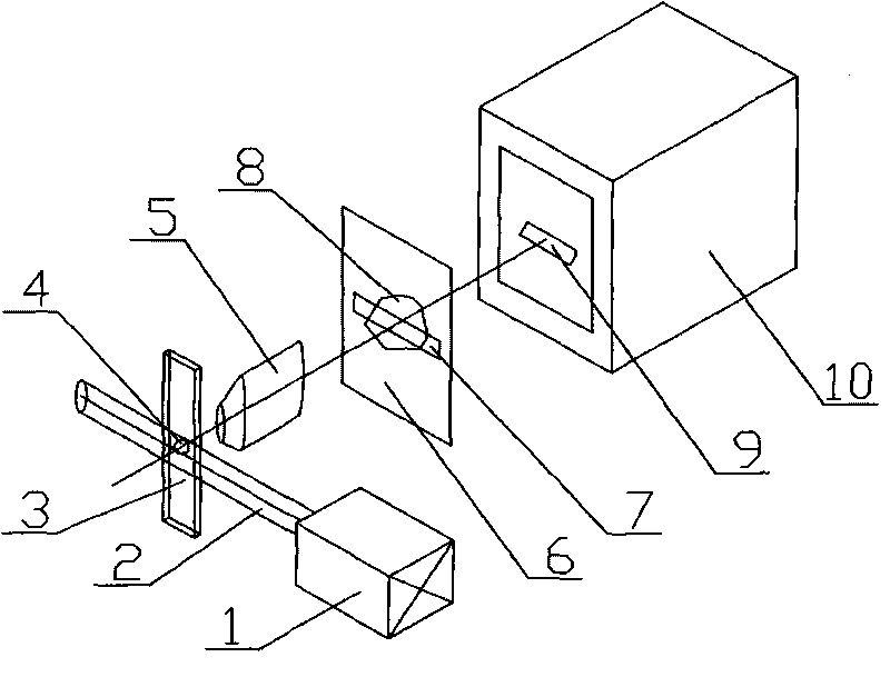
[0010] In the present invention, the excitation light is not shaped or slightly shaped, so that the spot size of the excitation light is still larger than the size of the sample, and at the same time irradiates the entire sample to excite fluorescence. On the image plane of the image space of the microscopic magnifying device or at an image distance less than one-fifth of the distance from the image plane, a long strip-shaped slit flat light barrier sheet is arranged, and the light barrier surface is perpendicular to the optical axis of the microscopic magnifying device , only the slit is light-transmitting, and other parts are treated to eliminate stray light to reduce stray light. The length direction of the slit is perpendicular to the sample flow direction, and the width direction is the same as the sample flow direction. The length of the slit is greater than the size of the image formed by the sample and not less than the width of the field of view of the microscope syst...


PUM


Abstract

The invention provides a fluorescent signal exciting and detecting device for a postpositive imaging diaphragm plate, and relates to a fluorescent optical signal detecting device. The device comprises an exciting light generator, a flow sample chamber, a micro-amplification device, a diaphragm plate and a fluorescence detecting device., and is characterized in that: a stripe slit diaphragm plate is arranged close to the image plane of image space of the micro-amplification device, and is vertical to the optical axis of the micro-amplification device; the length direction of the slit is vertical to the flowing direction of a sample, while the width direction is the same as the flowing direction of the sample; the length of the slit is greater than the size of an image generated by the sample, and is not less than the width of a visual field of the micro-amplification device; and the size of the width of the slit is less than the size of the image generated by the sample. The device has the advantages that: fluorescent signals can be detected under the condition of only displacing a planar diaphragm with a simple strip slit so as to acquire the shape information of the sample; and the planar diaphragm of the strip slit is thin, and has good manufacture process and low cost. The device can effectively prevent the diffraction effect generated by the diaphragm slit of the exciting light, and improve the signal-to-noise ratio.

Description

Technical field: [0001] The invention relates to a fluorescent light signal detection device, which is especially suitable for the flow cytometry fluorescent signal detection device. Background technique: [0002] Flow cytometry mainly adopts excitation light to excite sample particles to generate fluorescence, and then gathers the fluorescent signal to the fluorescence detection device through the microscopic amplification device for fluorescence signal detection, and checks the strength and duration of the fluorescence generated by the sample particles passing through the flow sample chamber. Time and other information for comprehensive analysis and judgment, so as to realize identification and counting. The device is composed of an excitation light generator, a flow sample chamber, a lens or a light block arranged between the excitation light generator and the fluid sample chamber, a fluorescence detection device, and a microscopic amplification device arranged between th...

Claims


Application Information

Patent Timeline
IPC IPC(8): G01N15/10G01N21/64
Inventor 张万祯王敏卓金寨
Owner FUJIAN NORMAL UNIV
Learn More