
Helmholtz coil-based electric conductivity nondestructive measurement system

A Helmholtz coil and measurement system technology, applied in the direction of material resistance, can solve the problems of positioning, resolution limitation, uneven magnetic field, shallow measurement depth, etc., achieve high resolution, increase information extraction, and improve measurement The effect of precision

Inactive Publication Date: 2012-11-07
STATE GRID SHANDONG ELECTRIC POWER
View PDF0 Cites 0 Cited by
  • Summary
  • Abstract
  • Description
  • Claims
  • Application Information

AI Technical Summary

Problems solved by technology

[0005] The excitation system of the existing measurement system uses an excitation coil on one side, and the magnetic field strength decays quickly, resulting in low sensitivity and shallow measurement depth; the uneven magnetic field leads to limited positioning and resolution

Method used


Image

  • Helmholtz coil-based electric conductivity nondestructive measurement system
  • Helmholtz coil-based electric conductivity nondestructive measurement system
  • Helmholtz coil-based electric conductivity nondestructive measurement system

Examples


Embodiment 1

[0026] Embodiment 1 The specific construction of the system

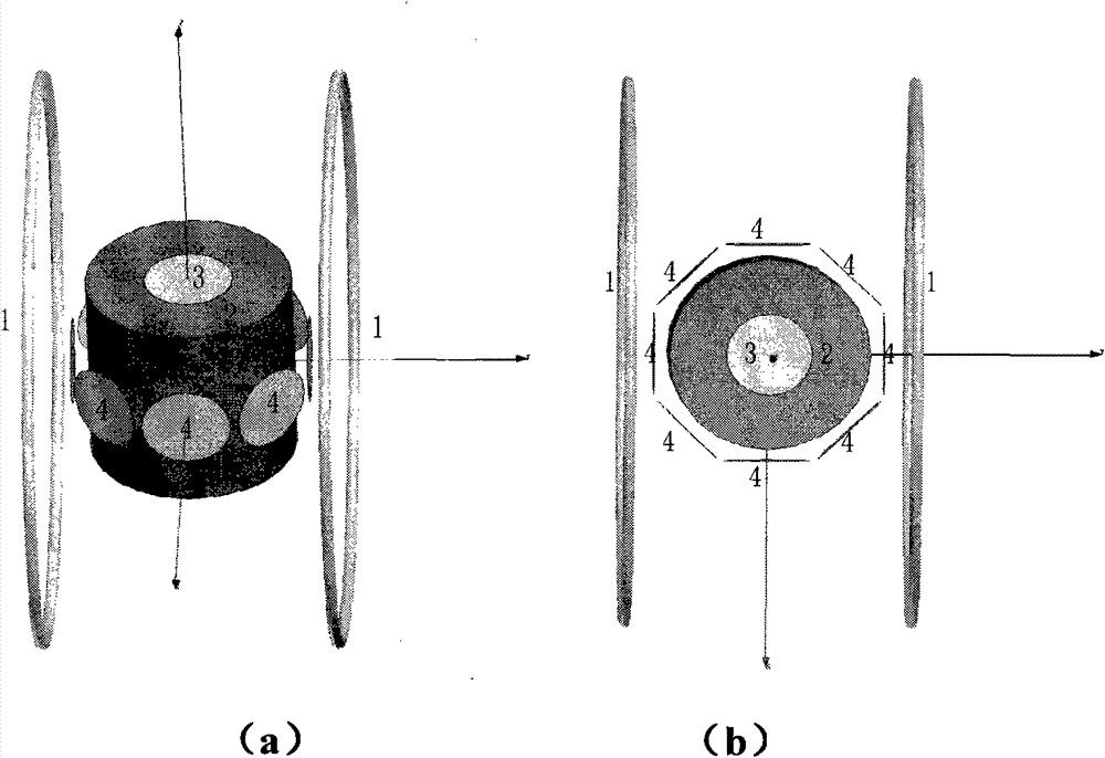
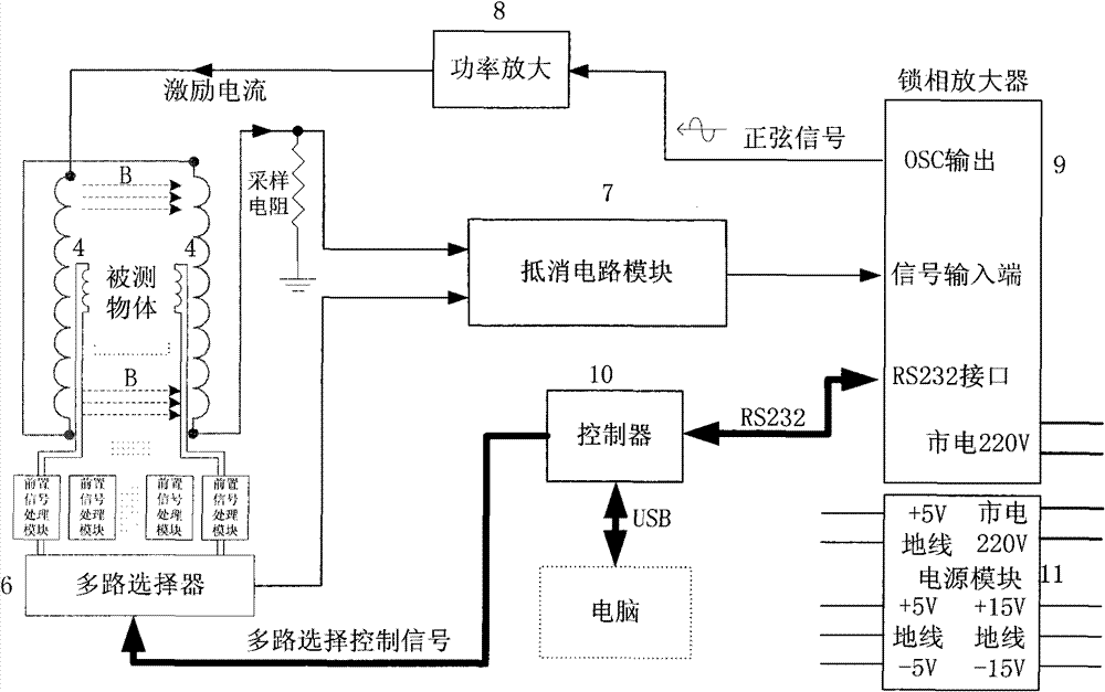
[0027] See attached figure 2 : the present invention comprises Helmholtz coil 1, detection coil 4, offset circuit, lock-in amplifier, controller and power supply, wherein:

[0028] 1) A time-varying uniform magnetic field B is constructed by the Helmholtz coil 1. In the embodiment, the parameters of the Helmholtz coil 1 are: inductance 67uH, DC impedance 234.8mΩ and distributed capacitance 3.7pF;

[0029] 2) In the above-mentioned uniform magnetic field, a number of detection coils 4 that can cut the magnetic force line are arranged in a single or annular interval; several coils are arranged around the ring, and the spacing of the coils can be adjusted according to different resolutions. If you want to locate the object For the damaged position, several coils should be arranged around the object. The more coils, the better the positioning effect; if it is only necessary to detect whether the object has cracks, it...

Embodiment 2

[0036] Embodiment 2 Comparison of the traditional system and the excitation magnetic field of the present invention

[0037] See attached Figure 6 , this is the magnetic field distribution diagram of the unilateral excitation coil of the traditional system. The magnetic field strength at the initial point is 0.0003T; at a distance of 10mm, the magnetic field strength is 0.00008T; at a distance of 20mm, the magnetic field strength is 0.00002T; at a distance of 25mm The magnetic field is already close to zero. It can be seen that the effective measurement distance of the traditional system is relatively shallow, and the magnetic field decays very quickly, and the magnetic field below 10mm is very weak.

[0038] See attached Figure 7 , the distribution diagram of the excitation magnetic field produced by the Helmholtz coil 1 of the present invention on the central axis, the magnetic field strength at its initial point is 0.000166T; the magnetic field strength at a distance of...


PUM


Abstract

The invention relates to a Helmholtz coil-based electric conductivity nondestructive measurement system, which comprises a Helmholtz coil, a detection coil, a bucking circuit, a lock-in amplifier, a controller and a power module, wherein the Helmholtz coil generates a uniformly-time-varying magnetic field; one or more detection coils capable of cutting magnetic lines are annularly distributed around a tested object in the magnetic field; and the induction voltages of different directions are continuously measured in a time-division way and are subjected to the processing of a phase shifting circuit, an amplitude modulation circuit and the like, and then phase and amplitude signals are sent to an upper computer. An excitation magnetic field is generated by the Helmholtz coil, which improves the strength and uniformity of the magnetic field, is favorable for improving the flexibility and measurement depth of the system and makes the positioning property good and the resolution high; oneexcitation magnetic field and a plurality of detection coils are utilized, which is favorable for improving the stability of the excitation magnetic field and reducing the influence of temperature onthe system; and the phase shifting circuit and the amplitude modulation circuit are added in a pre-posed circuit of each path of detection signals, which is favorable for increasing the amount of extracted information and improving measurement accuracy.

Description

technical field [0001] The invention relates to a conductivity measurement technology, in particular to a conductivity non-destructive measurement system based on a Helmholtz coil that can be used for medical image diagnosis or industrial flaw detection. technical background [0002] There are many methods to detect the quality of product technology and abnormal changes inside objects, but they can be summarized into two categories: one is the destructive method, and the other is the non-destructive testing method. The destructive method is a method of breaking open the inspected object to check its internal or surface quality. Although this method is highly accurate and relatively intuitive, it does not work in most cases: the purpose of manufacturing is to obtain finished products, and it is impossible to destroy one in order to check its quality; Most of the measured objects are not allowed to decompose and destroy, such as human diseased tissue. [0003] In order to ob...

Claims


Application Information

Patent Timeline
Patent Type & Authority Patents(China)
IPC IPC(8): G01N27/20
Inventor 何为罗海军徐征李冰王俊锋李倩
Owner STATE GRID SHANDONG ELECTRIC POWER
Learn More