Leaching equipment

A kind of equipment and leaching technology, which is applied in the direction of liquid solution solvent extraction, etc., can solve the problems of short service life, inability to meet the requirements of acid pulp leaching, low leaching efficiency, etc., and achieve the effect of long service life, high leaching efficiency and simple structure

Active Publication Date: 2010-06-09
WUHAN UNIV OF SCI & TECH
View PDF6 Cites 3 Cited by
  • Summary
  • Abstract
  • Description
  • Claims
  • Application Information

AI Technical Summary

Problems solved by technology

The leaching equipment still has short service life, low leaching efficiency, and can only be used for normal temperature pulp leaching, which cannot meet the requirements of acidic pulp leaching

Method used


Image

  • Leaching equipment
  • Leaching equipment
  • Leaching equipment

Examples


Embodiment 1

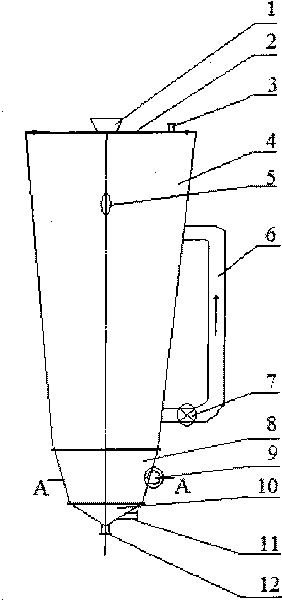
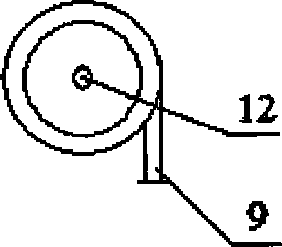
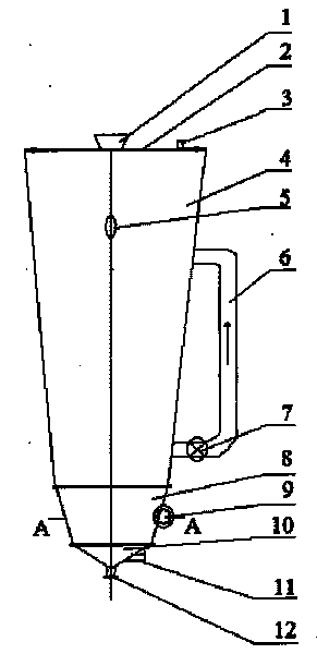
[0020] A kind of leaching equipment such as figure 1 Shown: Including the upper cone 4, the lower cone 8 and the bottom cone 10. The upper end of the upper cone 4 is fixedly connected with a cover plate 2, and the center of the cover plate 2 is provided with a feed port 1, and the cover plate 2 is provided with an exhaust hole 3 near the periphery; Observation hole 5, the shell of the upper cone 4 is equipped with a circulation pipe 6, the circulation pipe 6 communicates with the inner cavity of the upper cone 4, the pipe of the circulation pipe 6 is connected with a water pump 7; the lower port of the upper cone 4 and the lower cone The upper port of the body 8 is fixedly connected, the lower port of the lower cone 8 is fixedly connected with the upper port of the bottom cone 10, the shell of the lower cone 8 is provided with a steam inlet 9 which is located at a height of 0.48 of the lower cone 8, A flushing water inlet 11 is provided at the cone height of the bottom cone 10 ...

Embodiment 2

[0028] A leaching equipment, except for the following parameters, the rest are the same as in Example 1:

[0029] The steam inlet 9 is located at the height of the lower cone 8 at 0.52, the bottom cone (10) is provided with a flushing water inlet (11) at the cone height of 0.52; the ratio of the diameter of the upper port of the upper cone 4 to the lower port of the upper cone 4 1.8:1, the ratio of the height of the upper cone 4 to the diameter of the upper port of the upper cone 4 is 3.5:1; the lower end of the circulation pipe 6 is installed at a distance of 1 / 6 of the height of the upper cone 4 from the lower end of the upper cone 4 The upper end of the circulation pipe 6 is installed at 3 / 4 of the height of the upper cone 4 from the lower end of the upper cone 4; the ratio of the upper port diameter of the lower cone 8 to the lower port diameter of the lower cone 8 is 1.4:1 , The ratio of the height of the lower cone 8 to the diameter of the upper port of the lower cone 8 is ...


PUM


Abstract

The invention relates to leaching equipment which adopts the technical scheme: the upper end of an upper cone (4) is fixedly connected with a cover plate (2), and a feeding hole (1) is arranged in the center of the cover plate (2); an observation hole (5) is arranged at the upper part of a shell of the upper cone (4), the shell of the upper cone (4) is provided with a circulating tube (6), the circulating tube (6) is communicated with an inner cavity of the upper cone (4), and a pipeline of the circulating tube (6) is connected with a water pump (7); and a steam inlet (9) is arranged on a shell of a lower cone (8), and a discharge hole (12) is fixedly installed at the conical top part of a bottom cone (10). The shells of the equipment are both made of high temperature resistance glass fiber reinforced plastics, each inner wall is coated with acid resistance coatings, bolt connection is respectively used between the cover plate (2) and the upper cone (4), between the upper cone (4) and the lower cone (8), and between the lower cone (8) and the bottom cone (10), and a sealing ring is respectively padded at each connecting part. The invention has the advantages of simple structure, high leaching efficiency and long service life and can satisfy the requirements of temperature resistance and acid resistance.

Description

Technical field [0001] The invention belongs to the technical field of hydrometallurgy. Specifically relates to a leaching equipment. Background technique [0002] Leaching is the process of selectively leaching a certain component or some components in the solid material with an appropriate leaching agent to form a solution containing the metal to be extracted, and thereby initially separating it from other insoluble components. Currently commonly used leaching equipment mainly includes: [0003] (1) Gas agitation type leaching tank: The compressed air of the cavitation machine is used to supply air to the inflatable stirring device, and the compressed air entering the inflatable stirring device creates a stirring effect on the slurry. The operability of the equipment is poor, the stirring is insufficient, and the leaching efficiency is not high (Wang Chengzhao, Sun Weidong, Li Wenyu, etc. The application of the new aerated stirred leaching tank in the cyanidation process. Minin...

Claims


Application Information

Patent Timeline
Patent Type & Authority Applications(China)
IPC IPC(8): B01D11/04
Inventor 黄晶张一敏刘涛吴世洲陈铁军包申旭
Owner WUHAN UNIV OF SCI & TECH
Why Eureka
Try Eureka