Unlock instant, AI-driven research and patent intelligence for your innovation.

Micro bubble generator and method for generating micro bubbles by using same

A microbubble generator and microbubble technology, applied in chemical instruments and methods, mixing methods, fluid mixers, etc., can solve the problems of easy clogging of micropores, uneven size and distribution of microbubbles, and achieve good size distribution. , uniform size and distribution, good inflatable performance

Inactive Publication Date: 2010-06-09
KUNMING UNIV OF SCI & TECH
View PDF0 Cites 6 Cited by
  • Summary
  • Abstract
  • Description
  • Claims
  • Application Information

AI Technical Summary

Problems solved by technology

[0003] In order to overcome the problems of uneven size and distribution of microbubbles generated by the existing jet foaming technology, the present invention provides a microbubble generator and a method for producing microbubbles using the generator
This method combines the jet foaming technology and the microcellular foaming technology, through the external air supply, the jet foaming is uniform and sufficient, and the problem that the micropores are easy to be blocked is solved, and the turbulent flow generated by the jet is used to further crush the bubbles, so as to obtain fine and dense uniform microbubbles

Method used


Image

  • Micro bubble generator and method for generating micro bubbles by using same
  • Micro bubble generator and method for generating micro bubbles by using same
  • Micro bubble generator and method for generating micro bubbles by using same

Examples


Embodiment 1

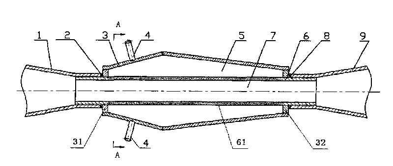
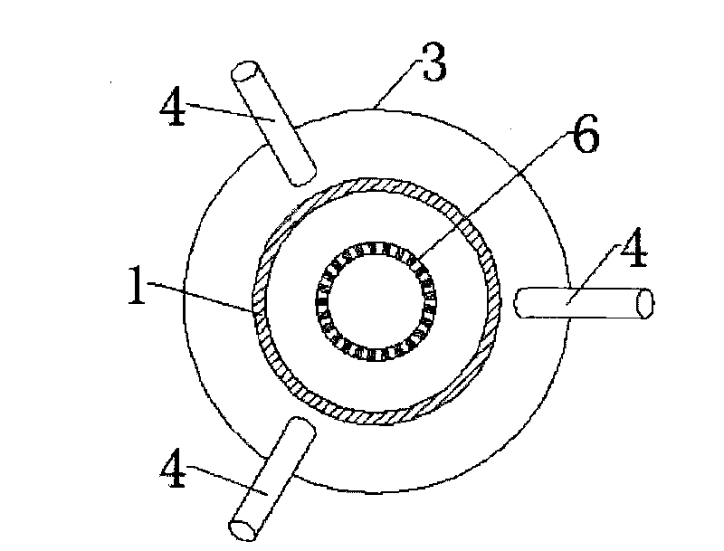
[0025] The microbubble generator 12 provided by the present invention comprises the liquid inner pipe 6 that has micropore 61 on its wall, and its two ends are respectively connected with nozzle 1 and diffusion port 9 by threads, and the liquid inner pipe 6 is provided with its inner belt cavity. Cavity 5, shell 3 with air inlet 4 on it, and the microporous pipe section of liquid inner pipe 6 is placed in the cavity 5 of shell 3, the micropore on the pipe section is connected with the cavity 5 of shell 3, wherein, shell 3 Two conical tubes are welded into a conical body with small ends and a large middle, and the end caps 31 and 32 are respectively welded at the two ports. Sealing rubber gaskets 2 and 8 are provided on the outer wall of the inner tube 6 between the port 9 and the corresponding end caps 31, 32. Three air inlets are evenly distributed along the circumference of the housing 3, and each air inlet is arranged on the surface of the housing. The air inlet pipe 4 that...

Embodiment 2

[0028] The situation is basically the same as in Example 1, except that the micropore diameter of the micropore section on the cylindrical surface of the microporous tube 6 is 20 μm.

Embodiment 3

[0030] The situation is basically the same as in Example 1, except that the micropore diameter of the micropore section on the cylindrical surface of the microporous tube 6 is 2 μm.


PUM

PropertyMeasurementUnit
Pore diameteraaaaaaaaaa

Abstract

The invention provides a micro bubble generator, which comprises a liquid inner pipe, wherein the wall of the liquid inner pipe is provided with micropores; and both ends of the liquid inner pipe are respectively provided with a nozzle and a diffusion port. The micro bubble generator is characterized in that: the outside of the liquid inner pipe is provided with a shell; the inside of the shell is provided with a cavity; the upper part of the shell is provided with an air inlet; a micropore pipe section of the liquid inner pipe is arranged in the cavity of the shell; and the micropores on the pipe section is communicated with the cavity of the shell. A method for generating micro bubbles by using the micro bubble generator is characterized in that ore slurry is sprayed into the inner pipe with the micropores to form a jet flow at high speed and negative pressure is generated in the inner pipe at the same time; and the air enters the inside of the cavity of the shell by an air inlet pipe, enters the inner pipe by the micropores under the action of the negative pressure and immediately generates the micro bubbles in the fluid of the inner pipe, and at the same time the micro bubbles are cut and crashed by the jet flow to form the uniform micro bubbles with different sizes. The micro bubble generator not only has simple structure, but also can effectively prevent the blockage of the micropores. The invention is suitable for various fields of the metal mine, the nonmetal mine, the coal, the paper making, the waste paper deinking, the industrial wastewater treatment and the like.

Description

technical field [0001] The invention relates to a microbubble generating device and a microbubble generating method for microbubble flotation in mineral processing, and is applicable to various fields such as metal and nonmetal mineral dressing, waste water treatment, and waste paper deinking. Background technique [0002] Micro-bubble flotation is a great innovation of flotation with a history of more than 100 years. It is widely used in various fields such as metal and non-metal beneficiation, wastewater treatment, and waste paper deinking. Micro-bubble flotation is based on the difference in surface properties of different solid minerals, and achieves separation through different effects on liquid and gas in the pulp. The size of the microbubble will directly affect its ability to carry mineral particles. Smaller microbubbles have a larger surface area per unit volume and carry more mineral particles per unit of air, which is conducive to increasing the probability of vi...

Claims


Application Information

Patent Timeline
IPC IPC(8): B01F5/02B01F3/04B03D1/14
Inventor 李浙昆李敏强艳丽樊瑜瑾李富玉
Owner KUNMING UNIV OF SCI & TECH