

Bevel positioning lathe fixture for precision forging bevel gear
A bevel gear and positioning car technology, applied in the field of car fixtures, can solve the problems of difficult design accuracy, inability to finish the shaft shoulder, high manufacturing cost, etc., and achieve the effect of compact structure, small overall size and less space occupation
- Summary
- Abstract
- Description
- Claims
- Application Information
AI Technical Summary
Problems solved by technology
Method used
Image

Examples
Embodiment Construction
[0014] The present invention will be further described below according to the accompanying drawings.
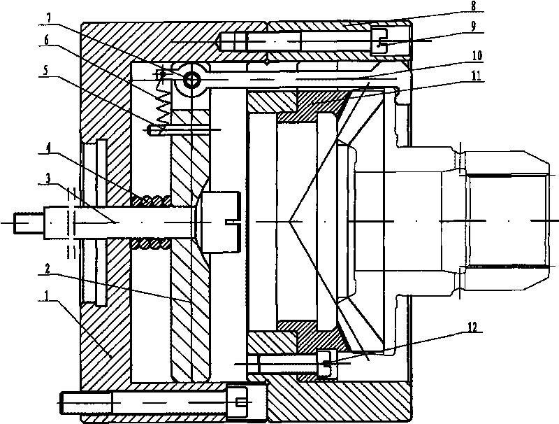
[0015] figure 1 The shown precision forging bevel gear bevel gear positioning car fixture includes two parts: a positioning structure and a clamping structure. The positioning structure includes a connecting plate 1 , a positioning plate 8 , a tooth mold 11 and bolts 9 . The clamping structure includes a claw seat 2 , a pull rod 3 , a tension spring 4 , a pin 5 , a tension spring 6 , a shaft pin 7 , a pull claw 10 and a screw 12 . The left end surface of the connection plate 1 is connected to the main shaft of the lathe, and the connection plate 1 has a built-in clamping structure, wherein the claw seat 2 and the connection plate 1 are in clearance fit, and a tension spring 4 is arranged between the parallel end surfaces, and the pull rod 3 is from right to left The pull claw seat 2, the tension spring 4 and the connection plate 1 are connected in series in sequence, and th...
PUM
 Abstract
Description
Claims
Application Information