Heat pump

A technology of heating pump and heating body, applied in the direction of pump, pump element, non-variable-capacity pump, etc., can solve the problems of increased material consumption, low heating efficiency, limited heating area, etc., to facilitate replacement and maintenance, and improve heating efficiency. , the effect of increasing the heating area

Inactive Publication Date: 2010-06-09
JOHNSON ELECTRIC SHENZHEN
View PDF6 Cites 12 Cited by
  • Summary
  • Abstract
  • Description
  • Claims
  • Application Information

AI Technical Summary

Problems solved by technology

[0004] Since the heating body 18' is wound between the impeller 16' and the volute 23', it is necessary to increase the inner cavity of the volute 23' to accommodate the heating body 18' during product design, resulting in an increase in the volume of the volute, Increase in materials
In addition, the volume of the inner cavity of the volute 23' is relatively large and the heating body 18' is only installed on the inner si

Method used


Image

  • Heat pump
  • Heat pump
  • Heat pump

Examples


Embodiment Construction

[0020] The present invention will be described in detail below in conjunction with the accompanying drawings.

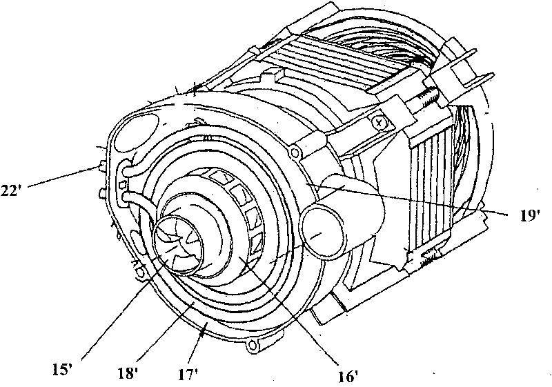
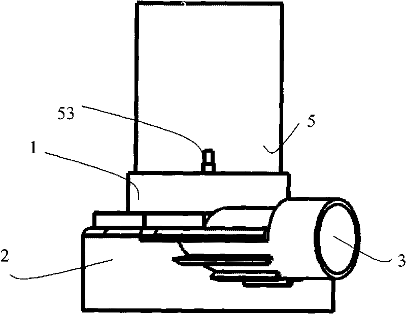
[0021] image 3 and Figure 4 It is a schematic diagram of the combination of the volute part and the electric heating equipment of the heat pump of the present invention. Because other parts of the heat pump of the present invention are the same or similar to the corresponding parts of the existing heat pump, therefore, image 3 and Figure 4 Other parts of the heat pump are not shown.

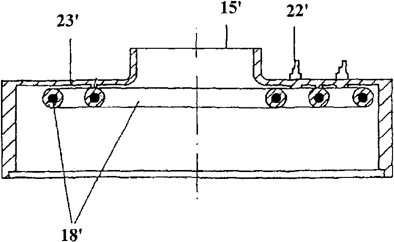
[0022] like image 3 , 4 As shown, the heat pump provided by the present invention includes an inlet 1, a volute 2 and an outlet 3 connected in sequence. An impeller (not shown in the figure) is installed in the volute 2, and a heating device 5 is installed at the inlet 1 . The heating device 5 is tubular, with one end connected to the inlet 1 and the other end used to connect to an external pipeline. The concrete structure of heating equipment 5 is as Figure 5 to Figure 7 ...


PUM


Abstract

The invention provides a heat pump comprising an inlet (1), a volute (2) and an outlet (3) which are successively communicated, wherein an impeller is installed in the volute (2). The heat pump also comprises heating equipment (5). The heating equipment (5) comprises a tubular heating body (51), a heat insulation protecting jacket (52) and a conductive terminal (53), wherein the heat insulation protecting jacket (52) surrounds the periphery of the tubular heating body (51), and the conductive terminal (53) is electrically connected with the tubular heating body (51) and passes through the heat insulation protecting jacket (52) to be connected with an external supply circuit; one end of the heating equipment (5) can be fixedly connected to the inlet (1) or the outlet (3); and the other end is used for connecting an external pipeline. The invention adopts the tubular heating body which is connected with the inlet of the volute and the external water pipe in series, which is convenient to heat flowing water, has large heating area and improves heating efficiency. In addition, the heating body is surrounded by the heat insulation protecting jacket so as to prevent the heat of the electrical heating body from emitting outwards, thus further improving heating efficiency.

Description

technical field [0001] The present invention relates to an electric pump, and more particularly, to a heat pump. Background technique [0002] The heat pump is an electric pump with heating function, which is widely used in dishwashers, washing machines and other fields. [0003] European patent application EP1047334 filed on 30.10.1999 discloses a heat pump. like figure 1 For the schematic diagram of the heat pump, figure 2 is a sectional view of the heat pump scroll portion. like figure 1 and figure 2 As shown, the heat pump includes a casing 19' and a motor (not shown) installed in the casing, an impeller 16' is installed at the inlet 15' of the heat pump, and a volute 23' is fixedly installed to the casing 19' to cover Impeller 16'. A heating device 17' is installed between the impeller 16' and the volute 23', the heating device 17' includes a heating body 18', and the heating body 18' surrounds the impeller 16' in concentric circles, and the wiring of the heati...

Claims


Application Information

Patent Timeline
IPC IPC(8): F04D29/58F04D29/62D06F39/04A47L15/42
CPCY02B40/44Y02B40/00
Inventor 阿瓦德·巴達方
Owner JOHNSON ELECTRIC SHENZHEN
Why Eureka
Try Eureka