Conductor connector for catenary continuous vulcanization of cross-linked cables and catenary continuous vulcanization preparation method for cross-linked cables
A cross-linked cable and wire connection technology, applied in the direction of conductor/cable insulation, etc., can solve the problems of difficult to meet the actual production requirements of CCV, insulation and shielding materials cannot be reused, and affect production efficiency, etc., to achieve catenary continuous Vulcanization, meet the eccentric requirements of rotation control, and improve production efficiency
- Summary
- Abstract
- Description
- Claims
- Application Information
AI Technical Summary
Problems solved by technology
Method used
Image
Examples
Embodiment 1
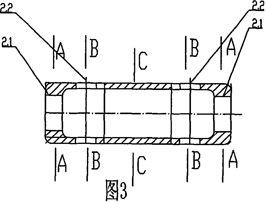
[0026] Embodiment 1: see figure 1 — Figure 7 , the cross-linked cable catenary type continuous vulcanized wire connector of the present invention includes compression sleeves 1.1 and 1.2 respectively used to connect two wires at the left and right ends, and a connecting sleeve 2 in the middle to form a traction rotatable connector in series ( figure 1 ). Among them, the connection wire compression sleeve 1.1, 1.2 ( figure 2 ), an integral structure consisting of three sections of a hollow crimping tube (sleeve for short) 5.1 with an outer diameter not greater than the diameter of the wire, a thin neck 5.2, and an embedded pulling head 5.3 with a diameter larger than the thin neck. The inner wall of the hollow crimping tube 5.1 is processed with The internal thread can increase the frictional force with the wire to ensure that the crimping is firm and reliable. The head 5.3 has a radial through hole 5.4 for inserting the anti-rotation pin. Intermediate linker 2 ( image 3...
Embodiment 2
[0027] Example 2: see Figure 8 , 9 , as in embodiment 1, wherein the continuous wire is a round wire concentric twisted wire. The intermediate connector is a connecting rod 6 with an enlarged spherical head 6.1 and 6.2 at both ends. The compression sleeve connecting the two wires is an integral structure composed of hollow crimping tubes 1.1.1 and 1.2.1 whose outer diameter is not larger than the diameter of the wires, and an axial blind hole connection part 1.1.2 and 1.2.2 at the other end. The end has a shrinkage cavity structure, and the blind hole section has a gap 1.6.1 that can be embedded in the sub-methine connecting rod. As mentioned above, there are radial through holes in the blind hole section and the head of the methionine for inserting anti-rotation pins. The CCV production method is basically the same as that of Example 1, the front and rear wires 4.1.1 and 4.2.1 are connected, and an outer layer is respectively stripped off and inserted into a compression s...
Embodiment 3
[0028] Embodiment 3: see Figure 10 , 11 , as mentioned above, the intermediate connector is omitted, and the non-connecting wire ends of the two connecting wire compression sleeves 1.1.3 and 1.2.4 respectively have the pulling head 1.1.7 in the structure of half sub-methine, and the pulling head 1.1.7 for pulling and inserting. The blind hole section 1.2.3 of the mouth, the blind hole section and the sub-methine head each have a radial insertion pin through hole 1.1.8, and the blind hole section has a gap 1.2.3 that can be embedded into the sub-methine head. When in use, the traction head of one compression sleeve is embedded, and the blind hole section of the other compression sleeve is provided with a constriction to form a rotatable traction connection, and the pin is inserted to be relatively fixed. The production method is basically the same as above.
PUM
 Abstract
Description
Claims
Application Information
 - R&D
- Intellectual Property
- Life Sciences
- Materials
- Tech Scout
- Unparalleled Data Quality
- Higher Quality Content
- 60% Fewer Hallucinations
Browse by: Latest US Patents, China's latest patents, Technical Efficacy Thesaurus, Application Domain, Technology Topic, Popular Technical Reports.
© 2025 PatSnap. All rights reserved.Legal|Privacy policy|Modern Slavery Act Transparency Statement|Sitemap|About US| Contact US: help@patsnap.com


