Transformer structure of microwave oven

A technology for transformers and microwave ovens, applied in the field of microwave ovens, can solve the problems of transformers with small ventilation and heat dissipation area, affect the heat dissipation efficiency of transformers, and the heat cannot be dissipated in time, and achieve the effects of facilitating ventilation and heat dissipation, reducing temperature, and reducing overall structural noise

Inactive Publication Date: 2010-06-09
LG ELECTRONICS (TIANJIN) APPLIANCES CO LTD
View PDF0 Cites 3 Cited by
  • Summary
  • Abstract
  • Description
  • Claims
  • Application Information

AI Technical Summary

Problems solved by technology

[0009] The transformer structure of the microwave oven in the prior art is fixed on the bottom plate, and the distance between the transformer and the shell of the microwave oven is only 1-3 centimeters. It will generate electromagnetic excitation to the nearby microwave oven casing, causing it to resonate, resulting in greater noise
In addition, the transformer will generate a lot of heat due to the internal resistance when it is working. The higher the voltage generated by the transformer, the greater the heat generation. However, the ventilation and heat dissipation area of ​​the transformer is small, so that the heat cannot be dissipated in time, thus affecting the heat dissipation efficiency of the transformer.

Method used


Image

  • Transformer structure of microwave oven
  • Transformer structure of microwave oven
  • Transformer structure of microwave oven

Examples


Embodiment Construction

[0022] The present invention will be described in detail below with reference to the drawings and embodiments:

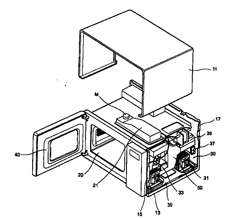
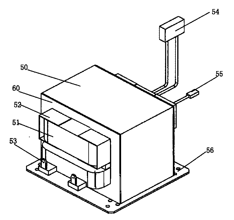
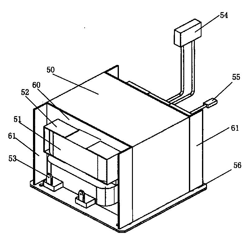
[0023] image 3 It is a schematic diagram of the transformer structure of the microwave oven of the present invention.

[0024] Such as image 3 As shown, the transformer structure of the microwave oven of the present invention includes: an iron core 50 formed by closely arranging a plurality of silicon steel sheets 60, so that a magnetic shunt with a high reluctance gap is formed in the transformer. A certain amount of leakage flux will be generated in the circuit, which controls the output current of the transformer to keep the working current of the magnetron relatively stable; the coil 51 wound on the iron core to generate a predetermined voltage passes through the primary coil and the secondary coil The interaction converts 220V mains power into a filament voltage of 3.3V or a working voltage of about 2100V; separates different groups of coils or separates the coi...


PUM


Abstract

The invention discloses a transformer structure of a microwave oven, comprising an iron core, a coil, an insulating strip, an incoming end, an output end and a fixed plate. A silicon steel disc positioned outmost the two ends of the iron core is provided with an anti-magnetic plate, the anti-magnetic plate is vertical to the silicon steel disc and erected at the two sides of the silicon steel disc to block a magnetic force line generated by magnetic leakage of the coil protruded on the iron core part. Therefore, the invention blocks electromagnet excitation of the microwave oven shell from a magnetic field generated by the magnet leakage of a coil winding terminal, avoids causing the microwave oven shell to resonate and reduces the noise of the integral structure during operation of the microwave oven. Besides, the anti-magnetic plate arranged on the silicon steel plate also increases the integral radiation area of the transformer, thereby the invention is more beneficial to ventilation and radiation of the transformer, effectively reduce the temperature of the transformer during the operation of the microwave oven and improve the radiation efficiency of the transformer.

Description

Technical field [0001] The present invention belongs to the technical field of microwave ovens, and specifically relates to an anti-magnetic plate provided on the outermost silicon steel sheets at both ends of the iron core to block the magnetic leakage generated by the coils protruding from the iron core part, avoiding resonance of the microwave oven shell, thereby effectively The transformer structure of the microwave oven can reduce the structural noise of the microwave oven. technical background [0002] A microwave oven is a device that generates microwaves by a magnetron after the power is turned on, and irradiates these microwaves on the food to be heated to cook the food. Such microwave ovens can be divided into household microwave ovens equipped with small magnetrons and commercial microwave ovens equipped with large or multiple magnetrons. Microwave ovens can also be classified according to the way of heating food. Household microwave ovens generally use the method of ...

Claims


Application Information

Patent Timeline
Patent Type & Authority Applications(China)
IPC IPC(8): H01F27/24H01F41/02F24C7/02
Inventor 满宏亮杨柱
Owner LG ELECTRONICS (TIANJIN) APPLIANCES CO LTD
Why Eureka
Try Eureka