Optical signal transmission processing method, sending device and system

A transmission device and optical signal technology, applied in the field of communication transmission, can solve the problems of reducing and limiting the optical transmission distance, unable to restore the carrier phase correctly, etc. Effect

Active Publication Date: 2010-06-09
HUAWEI TECH CO LTD
View PDF0 Cites 36 Cited by
  • Summary
  • Abstract
  • Description
  • Claims
  • Application Information

AI Technical Summary

Problems solved by technology

[0004] From the above-mentioned introduction to the optical transmission system of the prior art, the inventor found that the above-mentioned prior art has at least the following problems: the existing optical transmission system is affected by nonlinearity, and when the input power of the optical signal increases, the nonlinear effect l

Method used


Image

  • Optical signal transmission processing method, sending device and system
  • Optical signal transmission processing method, sending device and system
  • Optical signal transmission processing method, sending device and system

Examples


Embodiment 1

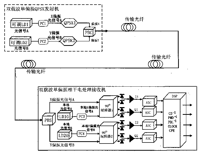
[0042] This implementation provides an optical signal sending device, the specific architecture see figure 2 The dual-carrier single-polarization QPSK transmitter part in the schematic diagram of the optical signal transmission system, the sending device specifically includes:

[0043] Sending end optical signal generating device, first polarization controller PC1, second polarization controller PC2, first quadrature phase shift keying modulator QPSK1 (Quadrature Phase Shift Keying, QPSK), second quadrature phase shift keying modulator QPSK2 , Polarization Beam Splitter (PBS);

[0044]Among them, the sending end optical signal generating device can generate optical signal A and optical signal B of different wavelengths, it is specifically composed of two lasers LD1 and LD2 as light sources at the sending end, and the lasers LD1 and LD2 respectively generate two carrier optical signals of different wavelengths (optical signal A and optical signal B); carry out polarization co...

Embodiment 2

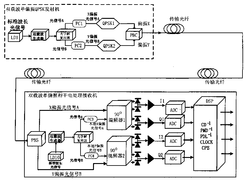
[0050] This implementation provides an optical signal sending device, see image 3 The dual-carrier single-polarization QPSK transmitter part in the schematic diagram of the optical signal transmission system, the sending device includes:

[0051] The optical signal generating device at the sending end, the first quadrature phase shift keying modulator QPSK1, the second quadrature phase shift keying modulator QPSK2, the first polarization controller PC1, the second polarization controller PC2, and the polarization beam combiner (Polarization Beam Splitter, PBS);

[0052] Among them, the optical signal generating device at the sending end can generate optical signals A and B of different wavelengths, and it is specifically composed of a laser LD1 as a light source, a dual-carrier generator and an optical demultiplexer demux, and the output of the laser LD1 is sequentially It is connected with the dual-carrier generator and optical demultiplexer. In actual operation, the laser ...

Embodiment 3

[0058] This implementation provides an optical signal transmission system, specifically as Figure 4 As shown in the schematic diagram of the optical signal transmission system, the system consists of a sending device (single-polarization dual-carrier QPSK transmitter) and a coherent electrical processing receiving device connected through an optical fiber, wherein the sending device can be the same as that given in the first and second embodiments above. The structure of the outgoing sending device is the same and will not be repeated here.

[0059] For the specific architecture of the coherent electrical processing receiving device, see Figure 4 The single-polarization dual-carrier coherent electrical processing receiver part in the schematic diagram of the optical signal transmission system includes:

[0060] Power divider splitter, optical signal generating device at the receiving end, first 90-degree mixer 1 (90°Hybrid), second 90-degree mixer 2, balanced receiving devi...


PUM


Abstract

The embodiment of the invention relates to the field of communication transmission, and discloses an optical signal transmission processing method, an optical signal sending device and an optical signal transmission system. The optical signal sending device comprises a sending end optical signal generating device, a first polarization controller, a second polarized controller, a first quarternaryphase-shift keying modulator, a second quarternary phase-shift keying modulator and a polarization beam combiner, wherein the sending end optical signal generating device is used for generating an optical signal A and an optical signal B with different wavelengths; the first polarization controller is used for carrying out polarization control for the optical signal A and generating an X polarization optical signal A; the second polarized controller is used for carrying out polarization control for the optical signal B and generating a Y polarization optical signal B; the first quarternary phase-shift keying modulator is used for modulating the X polarization optical signal A; the second quarternary phase-shift keying modulator is used for modulating the Y polarization optical signal B; and the polarization beam combiner is used for combining the modulated X polarization optical signal A and the modulated Y polarization optical signal B into a dual-carrier single-polarization optical signal. The invention enables the nonlinear effect in an optical fiber to be inhabited, enhances the nonlinear tolerance limit and the fiber feeding power of the optical signal transmission system andextends the transmission distance.

Description

technical field [0001] The present invention relates to the field of communication transmission, in particular to an optical signal transmission processing method, sending device and system. Background technique [0002] With the increase of single-wavelength transmission rate, the damage of optical signal in the transmission fiber has become a key issue in high-speed optical transmission system. Coherent reception can linearly convert the damage in the optical domain to the electrical domain, and use the electrical domain to process and compensate the dispersion and polarization of the line. Mode dispersion PMD damage is an important technical means in the current high-speed transmission processing, but the disadvantage of this processing method is that it is limited by nonlinear effects. [0003] like figure 1 As shown, the processing method in the prior art is to perform four phase shifts in the X polarization direction and Y polarization direction of the single-waveleng...

Claims


Application Information

Patent Timeline
IPC IPC(8): H04J14/06H04B10/148H04B10/556H04B10/60
Inventor 李良川
Owner HUAWEI TECH CO LTD
Why Eureka
Try Eureka