Transfer device and vacuum processing apparatus using the same

A technology of conveying device and conveying room, which is applied in the direction of conveyor objects, transportation and packaging, program control manipulator, etc., to achieve the effect of heavy load and long life

Active Publication Date: 2010-06-09
ULVAC INC
View PDF8 Cites 12 Cited by
  • Summary
  • Abstract
  • Description
  • Claims
  • Application Information

AI Technical Summary

Problems solved by technology

[0024] The present invention is made to solve such problems of the prior art, and its object is to provide a conveying device that does not cause the problem of contamination of the vacuum device and the like with grease and the like.

Method used


Image

  • Transfer device and vacuum processing apparatus using the same
  • Transfer device and vacuum processing apparatus using the same
  • Transfer device and vacuum processing apparatus using the same

Examples


Embodiment Construction

[0078] Hereinafter, preferred embodiments of the present invention will be described in detail with reference to the drawings.

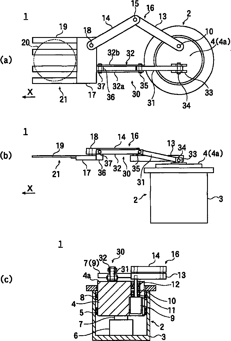
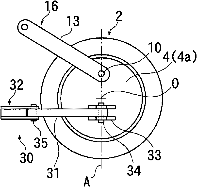
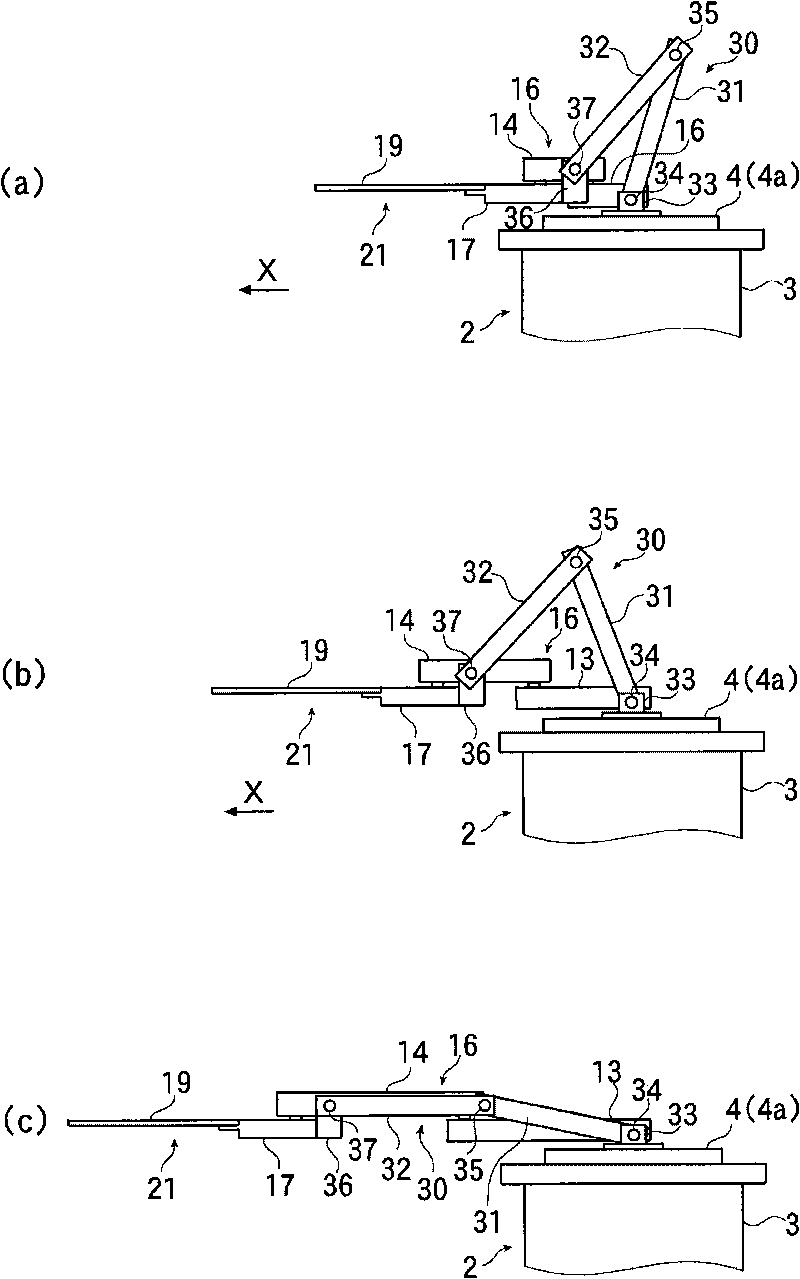
[0079] figure 1 (a)-(c) show the schematic structure of embodiment of the conveying apparatus of this invention, figure 1 (a) is a plan view, figure 1 (b) is a side view, figure 1 (c) is an internal configuration diagram. in addition, figure 2 It is an explanatory plan view showing the installation position of the guide mechanism in the conveying device.

[0080] like figure 1 As shown in (a) to (c), the conveying device 1 according to the present embodiment is configured to have a cylindrical casing 3 serving as the device main body 2 , and a turntable 4 is accommodated in the casing 3 .

[0081] The turntable 4 is formed in a cylindrical shape, and is rotatably attached to the inner wall of the casing 3 via a bearing 5 .

[0082] A drive motor 6 is arranged on the bottom surface of the cabinet 3 , and the front end of a rotary shaft 7 ...


PUM


Abstract

A transfer device that avoids the problem of a vacuum apparatus being contaminated by grease, dust, and others and having a small base area is provided. Corrosion protection according to an existing technology may be applied to the transfer device. The transfer device may have a transfer section to support and transfer an object to be transferred, a link to transmit power from a device main body to the transfer section and move the transfer section in the horizontal direction, and a guide mechanism disposed between the device main body and the transfer section guide. The guide mechanism may have pivotally connected first and second guide arms. The first guide arm at one end of the guide mechanism may be attached to the device main body, and the second guide arm at the other end thereof may be attached to the transfer section.

Description

technical field [0001] The present invention relates to a transfer device for a substrate to be processed, such as a semiconductor wafer, and more particularly to a vacuum processing apparatus equipped with one or a plurality of process chambers suitable for processing a substrate to be processed. The in and out conveying device. Background technique [0002] Conventionally, as such a conveying device, the conventional example disclosed in Unexamined-Japanese-Patent No. 2005-125479 is mentioned, for example. [0003] Figure 8 (a) to (c) show the basic configuration of the prior art. [0004] like Figure 8 As shown in (a) to (c), in this conveyance device 200, a long guide member 202 is fixed to a turntable 201 rotatable in the horizontal direction. Furthermore, one end of the first arm 203 is attached to a drive motor (not shown) in a rotatable state about the base 202a penetrating the guide member 202 and the support shaft 203a of the turntable 201 . [0005] A linear ...

Claims


Application Information

Patent Timeline
Patent Type & Authority Applications(China)
IPC IPC(8): B25J9/06B65G49/07H01L21/677
CPCB25J9/046B25J9/0072B25J17/0266H01L21/67742B25J9/042B25J9/0048B25J11/0095H01L21/68707
Inventor 南展史藤村和广
Owner ULVAC INC
Why Eureka
Try Eureka