Method for machining cylindrical gear cutting teeth

A processing method and technology of cylindrical gears, applied in belts/chains/gears, gear teeth, components with teeth, etc., can solve the undeveloped technology, unacceptable cost of spiral broaching, low precision of broaching process, etc. question

Inactive Publication Date: 2010-06-16
TIANJIN UNIV +1
View PDF0 Cites 25 Cited by
  • Summary
  • Abstract
  • Description
  • Claims
  • Application Information

AI Technical Summary

Problems solved by technology

However, with the development and progress of technology, these processing methods can no longer meet the process requirements and precision requirements of some products.
For example, the internal gear processing of the planetary gear sleeve of the automatic transmission of the automobile, due to the space limitation, the gear hobbing and milling process becomes impossible; due to the consideration of the compact structure, the internal gear is often not penetrated, and no empty tool is designed inside slots and other process structures, which also limits the realization of the gear shaping and tooth drawing process; for the axially penetrating internal teeth, the gear shaping or tooth drawing process can be used, but the efficiency and machining accuracy of the gear shaping process are not high, and the gear drawing process accuracy Low cost and high cost, especially for large-diameter helical internal gear processing, the cost of helical broach is unacceptable
After entering the 21st century, some foreign companies have adopted the method of processing internal splines to process internal teeth, and have achieved preliminary results but have not yet formed a mature technology.

Method used


Image

  • Method for machining cylindrical gear cutting teeth
  • Method for machining cylindrical gear cutting teeth
  • Method for machining cylindrical gear cutting teeth

Examples


Embodiment Construction

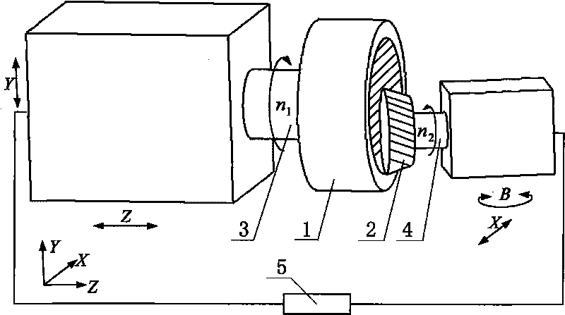
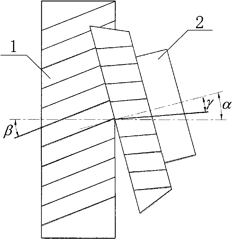
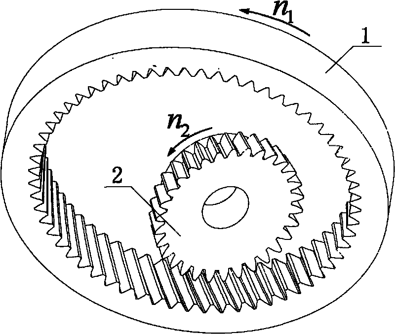
[0010] The following is attached Figure 1~4 And the principle of the present invention will be further illustrated by examples. In gear processing, the most common inner tooth of the gear sleeve is an involute tooth shape, and the direction of the tooth line can be a straight line or a helical line (such as figure 1 shown). Its rotating speed of the main shaft 3 of workpiece 1 of the present invention is n 1 , the speed of spindle 4 of tool 2 is n2, n 1 with n 2 The ratio is equal to the ratio of the number of tool teeth to the number of workpiece teeth. During processing, the axis of the workpiece spindle and the axis of the tool spindle form an axial angle α, and the angle α is the algebraic sum of the workpiece tooth helix angle β and the tool tooth helix angle γ (such as figure 2 ). The blade shape of the tool 2 is designed to be a conjugate shape with the tooth shape of the workpiece 1 . The multi-axis motion controller 5 controls the workpiece 1 and the tool 2 ...


PUM


Abstract

The invention discloses a method for machining cylindrical gear cutting teeth. The rotation speeds of a workpiece and a cutter are n1 and n2 respectively, the ratio of the n1 to the n2 is equal to the ratio of the tooth number of the cutter and the workpiece, and the cutter is equivalent to a gear engaged with the workpiece. During machining, the axes of two main shafts of the workpiece and the cuter form a crossed axis angle alpha, and the angle alpha is the algebraic sum of a tooth directional spiral angle beta of the workpiece and a tooth directional spiral angle gamma of the cutter. The blade shape of the cutter is designed to be conjugate with the tooth shape of the workpiece; the rotations of the workpiece and the cutter are controlled by a multi-axis movement controller; and the cutter has axial feed and radial feed. At a cutting point, the cutting speed V is changed along with the change of the cutting point on the blade to form a cutting action so as to finish cutting and shaping of a gear tooth surface of the workpiece. The machining for a non-penetrating involute inner tooth can be finished without a tool withdrawal groove and cannot be finished by the existing gear machining technology. An inserting tooth and a pull tooth can be replaced, the machining precision and efficiency can be improved, and the manufacturing cost can be greatly reduced.

Description

technical field [0001] The invention belongs to the technical field of mechanical processing, and in particular relates to a processing technical method of a cylindrical gear. Background technique [0002] In the field of machining, the processing technology from the blank to the surface forming of the cylindrical gear tooth is divided into two types of processing technologies based on the generation method and the forming method. Generative processing includes gear hobbing and gear shaping, and forming processing includes gear milling and broaching. These processing methods have been developed relatively mature and widely recognized in the gear processing industry. However, with the development and progress of technology, these processing methods can no longer meet the process requirements and precision requirements of some current products. For example, the internal gear processing of the planetary gear sleeve of the automatic transmission of the automobile, due to the s...

Claims


Application Information

Patent Timeline
Patent Type & Authority Applications(China)
IPC IPC(8): B23F17/00
CPCB23F5/163
Inventor 李佳陈新春李锡晗
Owner TIANJIN UNIV
Why Eureka
Try Eureka