Waste circuit board hook pulling and dismounting device

A technology for waste circuit boards and dismantling devices, which is applied in the direction of electronic waste recycling, solid waste removal, and tool manufacturing, and can solve the problem that the overall disassembly equipment of waste circuit boards is not well solved, and cannot provide circuit board plane force, The circuit board cannot be well sealed and other problems, so as to achieve the effect of fast heating, avoiding mutual temperature, and avoiding harm

Inactive Publication Date: 2010-06-16
TSINGHUA UNIV
View PDF13 Cites 21 Cited by
  • Summary
  • Abstract
  • Description
  • Claims
  • Application Information

AI Technical Summary

Problems solved by technology

Its disadvantages are: the circuit board cannot be well sealed when it is installed in the device, and the lower surface of the circuit board is not easy to generate a large negative pressure; the roller brush can only provide force parallel to the plane of the circuit board, and cannot provide force perpendicular to the circuit board. The force of the plane, so the plug-in components cannot be removed
So far, all the integrated dismantling equipment of waste circuit boards based on component reuse have not solved this problem well

Method used


Image

  • Waste circuit board hook pulling and dismounting device
  • Waste circuit board hook pulling and dismounting device
  • Waste circuit board hook pulling and dismounting device

Examples


Embodiment 1

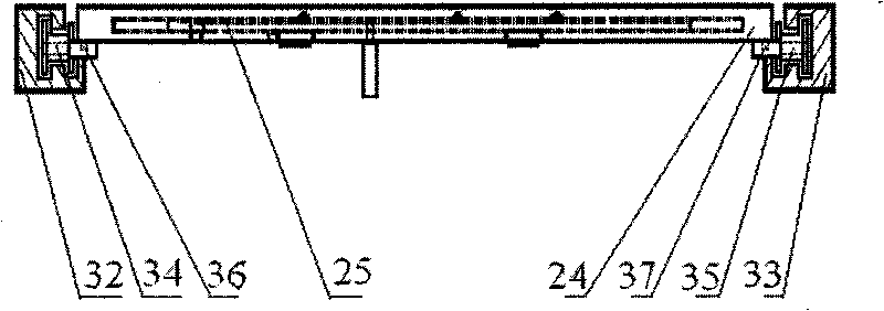
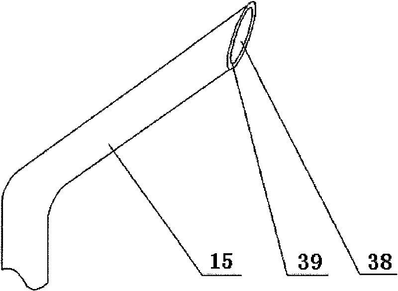
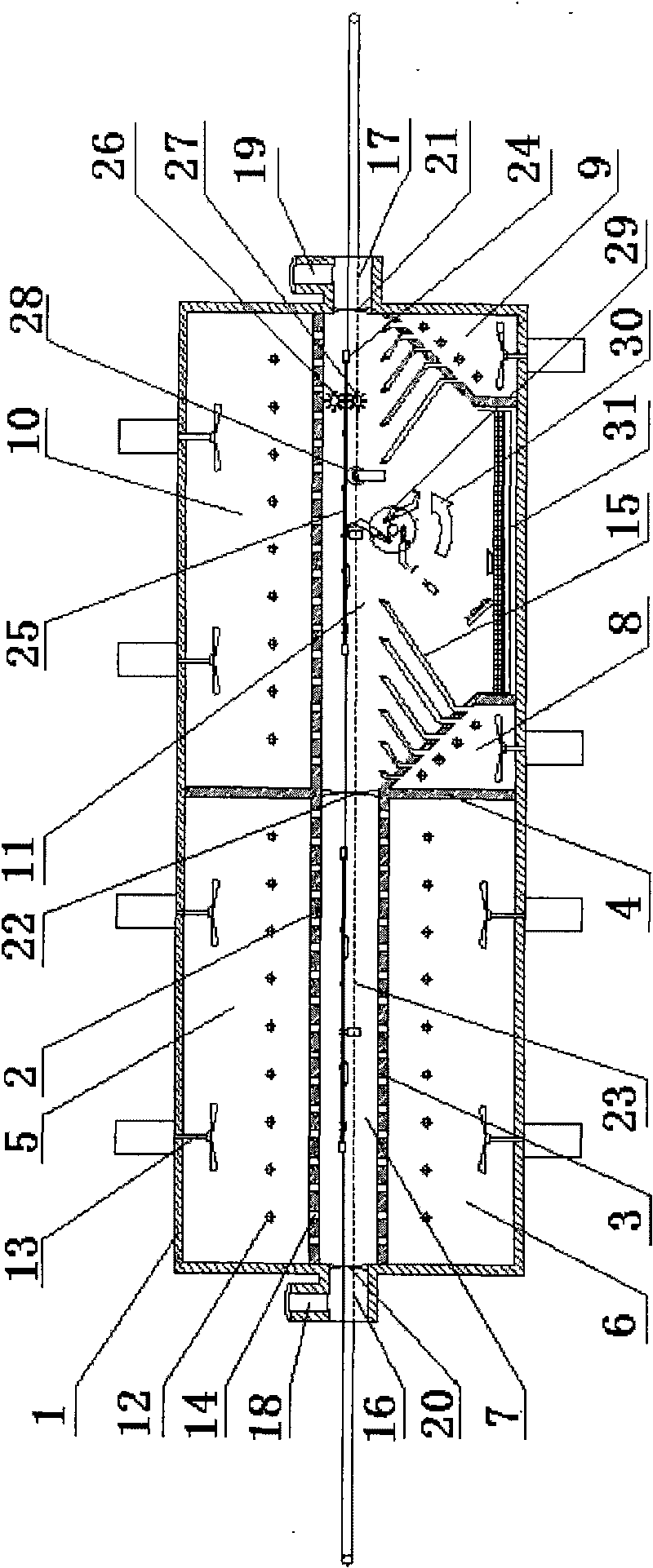
[0046] join figure 1 , The hooking and dismounting device for waste circuit boards in this embodiment includes a chassis, a heating system, a double chain transmission mechanism, a hooking mechanism, and a double roller brush mechanism. The upper partition 2, the lower partition 3 and the vertical partition 4 divide the space of the cabinet 1 into the upper preheating air box 5, the lower preheating air box 6, the preheating zone 7, the upper high temperature bellows 10 and the high temperature zone 11, and the high temperature zone There are hook pull mechanism 29, supporting wheel 28, upper steel wire roller brush 26 and lower steel wire roller brush 27, and there is a component and solder collection plate 31 under the high temperature zone 11, which separates the surrounding environment from the preheating zone 7 and is an entrance flexible partition 20. Separate the preheating zone 7 and the high temperature zone 11 as an intermediate flexible partition 22, and separate th...

Embodiment 2

[0060]In order to simplify the structure of the hook-pull mechanism in Embodiment 1 and reduce the manufacturing difficulty, this embodiment adopts the method of integrating the return coil spring and the hook.

[0061] see Figure 7 , the hook pulling mechanism of this embodiment is composed of coil spring hooks 48 and anti-swing washers 49 alternately strung on the secondary rotating shaft 42. The short end of the coil spring hook 48 is pressed on the main rotating shaft 41, and the middle part of the long end of the hook is pressed on the On the limit rod 43, the direction of the crotch is the same as the rotation direction 30 of the hook pulling mechanism, and the adjacent coil spring hooks 48 are separated by anti-swing washers 49. The hooking mechanism of this embodiment uses a coiled spring hook 48 to replace the rigid hook 44 and the return spring 46 of the first embodiment. The coiled spring hook 48 can not only hook and pull out components, but also automatically res...

Embodiment 3

[0064] see Figure 8 , the present embodiment further simplifies the hooking mechanism. The main rods of 8 elastic hooks 51 are affixed on the outer circle of the elastic hook rotating column 50 by the opposite direction of the hook pulling mechanism rotation direction 30, and the pointing of the crotch is identical with the hook pulling mechanism rotation direction 30, and a plurality of elastic hook rotating columns 50 is connected in series on the main rotating shaft 41. The bending of the elastic hook 51 itself can make it rotate at a certain angle, and can also reset automatically, so the secondary rotating shaft 42 and the reset coil spring 46 in the first embodiment are not required. Such as Figure 8 As shown, the rotation direction of the hook pulling mechanism is counterclockwise when it works, and in the rotation direction, the fixed end of the elastic hook 51 is located in front of the tip of the hook.

[0065] The advantage of this embodiment is that the mechan...


PUM


Abstract

The invention discloses a waste circuit board hook pulling and dismounting device, belonging to the technical field of waste recovery and reuse. The waste circuit board hook pulling and dismounting device comprises a crate, a heating system, a double-chain delivery mechanism, a hook pulling mechanism and a double-rolling brush mechanism, wherein the heating system divides the crate into a pre-heating region and a high temperature region; and a circuit board is arranged on the double-chain delivery mechanism, is preheated by the preheating region, and is subjected to dismounting of components and solder by the hook pulling mechanism and the double-rolling brush mechanism in the high temperature region. The air-out inclined planes of two lower high temperature bellows arranged at the lower part of the high temperature region inclines at a large angle facing to the center of the high temperature region, extension type hot air nozzles on the air-out inclined planes are a group of hot air spray pipes, the diagonal fault planes of the hot air spray pipes inclining upwards and the spray pipe outlets not only enable the circuit board to be heated evenly and rapidly, but also can ensure that all dismounted components and solder can enter collection trays of components and solder without entering the spray pipe outlets. The invention is a device which can pull and dismount the components from the printed circuit board with no damage and integrity, and is used for waste recover and reuse enterprises in electronic industry.

Description

technical field [0001] The invention belongs to the technical field of production, maintenance and recycling of waste products, and relates to a device for hooking and removing waste circuit boards. Background technique [0002] Printed Circuit Board (PCB for short) is an important part of electronic information products and household electrical appliances. As a large number of electronic and electrical products have been eliminated, printed circuit boards have been abandoned. Circuit boards contain a variety of toxic and harmful substances, and direct disposal will pollute the environment. The waste circuit board as a whole has lost its use value, but most of the components on the board are still in the middle of their service life, and can be downgraded and reused after being disassembled and repaired. In addition, dismantling components is also a process of sorting and enriching different substances, which is conducive to subsequent material recovery. At present, most ...

Claims


Application Information

Patent Timeline
Patent Type & Authority Applications(China)
IPC IPC(8): B23P19/04B09B3/00
CPCY02P70/10Y02W30/82
Inventor 段广洪向东龙旦风牟鹏魏威
Owner TSINGHUA UNIV
Why Eureka
Try Eureka