Al technical title is built by PatSnap Al team. It summarizes the technical point description of the patent document.
A magnetron sputtering and sputtering technology, which is applied in the direction of sputtering plating, ion implantation plating, metal material coating technology, etc., can solve the problems of burning out the electromagnetic coil, failing to meet the magnetic field requirements, and being unstable , to achieve the effect of prolonging the practical life, low cost and simple structure
Active Publication Date: 2010-06-16
SHENYANG SCI INSTR RES CENT CHINESE ACAD OF SCI
View PDF0 Cites 21 Cited by
Summary
Abstract
Description
Claims
Application Information
AI Technical Summary
This helps you quickly interpret patents by identifying the three key elements:
Problems solved by technology
Method used
Benefits of technology
Problems solved by technology
[0004] 1. During the energization process, the magnetic field generated by the energized coil is not stable due to the influence of grid voltage, coil turns, coil material and human factors, and the quality of the film prepared under the same conditions is not necessarily the same;
[0005] 2. During the working process of the target, due to the limitation of the structure, the expected magnetic field requirements are often not met. If you want to increase the current to reach the expected magnetic field strength, you often burn out the electromagnetic coil;
[0006] 3. The cost of the electromagnetic target is also much higher than that of the permanent magnet target. In addition to a DC power supply, an excitation power supply is required, and the cost is about 1.5 times that of the permanent magnet target.
Method used
Image
Click on the blue label to locate the original text in one second.
Reading with bidirectional positioning of images and text.
Examples
Embodiment Construction
[0016] The structure and principle of the present invention will be described in further detail below in conjunction with the accompanying drawings.
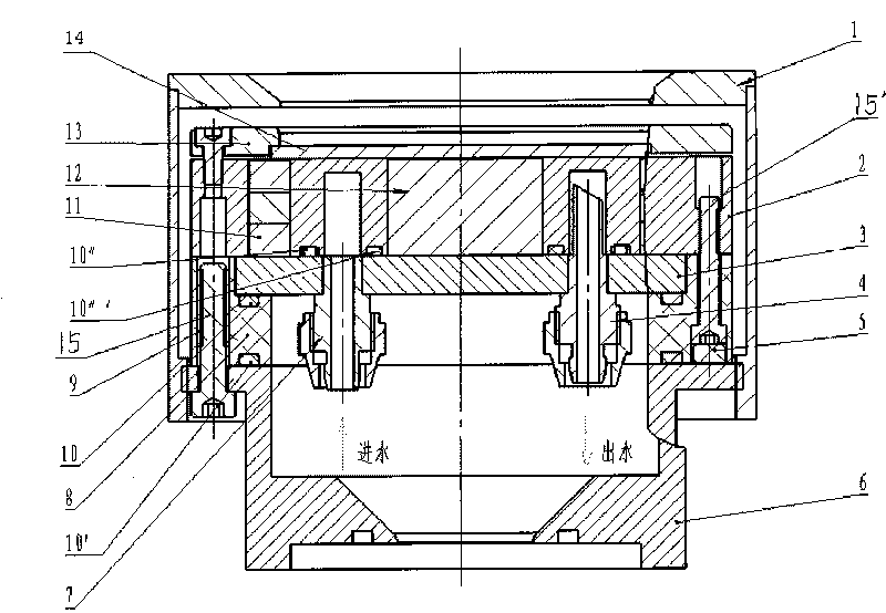
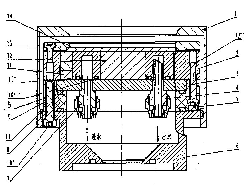
[0017] Such as figure 1 As shown, a circular planar magnetron sputtering target of a permanent magnet capable of sputtering magnetic materials, including an outer shield 1, a magnetic steel seat 2, a pole shoe 3, an insulating seat 8, a fixing seat 6, and a target cover 13. Inner magnetic steel 12, outer magnetic steel 11, water inlet nozzle 7, water outlet nozzle 4, connecting bolts and sealing rubber rings 10, 10′, 10″, 10″′; the target material 14 is directly placed on the magnetic steel base 2 , fixed by the target gland 13; the material of the magnetic steel seat 2 is oxygen-free copper, the inner magnetic steel 12 is placed in the center, and a few small holes are drilled around the periphery to place the outer magnetic steel 11, and the polarity of the inner magnetic steel 12 and the outer magnetic steel 11 are opposite ...
PUM
Abstract
The invention discloses a permanent-magnet magnetic control sputtering target with a round plane, which can sputter magnetic materials and is composed of an outer shield cover, a magnetic steel seat, a pole shoe, an insulating seat, a permanent seat, a target gland bush, inner magnetic steel, outer magnetic steel, a water inlet nozzle, a water outlet nozzle, an attachment bolt, a hermetical rubber, and the like, wherein a thread manual adjustable structure is adopted between the outer shield cover and the permanent seat, the materials of the magnetic steel seat are oxygen-free copper, the inner magnetic steel is arranged at the center of the magnetic steel seat, the periphery of the magnetic steel seat is drilled to form a plurality of pinholes for installing the outer magnetic steel, and target materials are directly laid on the magnetic steel seat and fixed by the target gland bush. The pole shoe is made of permeability materials, when the magnetic control target works, a direct current or radio-frequency power supply is applied to the pole shoe, the water inlet nozzle and the water outlet nozzle are welded by argon arc welding under the pole shoe, cooling water enters from a low place and outflows from a high place, and hermetical seal is realized by the hermetical rubber ring. The materials of the insulating seat are temperature-resistant insulating materials which can be used in vacuum, and are installed between the permanent seat (anode) and the pole shoe (cathode), and an insulating cap has the insulating action between an electriferous screw (cathode) and the permanent seat (anode). The invention has simple structure and low cost.
Description
technical field [0001] The invention relates to the field of coating equipment, in particular to a circular planar magnetron sputtering target capable of sputtering permanent magnets of magnetic materials. Background technique [0002] At present, in the field of domestic film preparation, magnetron sputtering is usually used as the mainstream of sputtering technology. The main reason is that magnetron sputtering has the characteristics of "high speed" and "low temperature". material film. The ordinary circular planar permanent magnet target technology capable of sputtering non-magnetic materials has been quite mature, and there are generally two types of magnetron targets capable of sputtering magnetic materials such as iron, nickel, and cobalt, one is an electromagnetic target, and the other is a magnetron target. One is a circular planar strong magnetic target modified from an ordinary circular planar permanent magnet target. [0003] However, electromagnetic targets ha...
Claims
Application Information
Patent Timeline
Application Date:The date an application was filed.
Publication Date:The date a patent or application was officially published.
First Publication Date:The earliest publication date of a patent with the same application number.
Issue Date:Publication date of the patent grant document.
PCT Entry Date:The Entry date of PCT National Phase.
Estimated Expiry Date:The statutory expiry date of a patent right according to the Patent Law, and it is the longest term of protection that the patent right can achieve without the termination of the patent right due to other reasons(Term extension factor has been taken into account ).
Invalid Date:Actual expiry date is based on effective date or publication date of legal transaction data of invalid patent.
Patent Type & Authority Applications(China)
IPC IPC(8): C23C14/35
Inventor 冯彬鲁向群佟辉刘大为周颖刘丽华
Owner SHENYANG SCI INSTR RES CENT CHINESE ACAD OF SCI