Torque-withstanding drill pipe elevating device

An elevator and drill pipe technology, which is applied to drill pipes, drill pipes, drilling equipment, etc., can solve the problems of large well site occupation, low drill pipe efficiency, and large wellhead space, so as to reduce the operating space and improve the operation. Efficiency, the effect of reducing labor intensity

Active Publication Date: 2010-06-16
BC P INC CHINA NAT PETROLEUM CORP +1
View PDF0 Cites 19 Cited by
  • Summary
  • Abstract
  • Description
  • Claims
  • Application Information

AI Technical Summary

Problems solved by technology

Adopting conventional elevators to carry out the drilling pipe operation method has the following disadvantages: 1) it takes up a lot of wellhead space
The power faucet cannot be used for the spinner of the drill pipe. The wellhead needs to be equipped with hydraulic tongs or spinner tools for the spinner operation. In order to install and operate the wellhead tools, a large wellhead working area is required, resulting in large volume and heavy weight of the drill floor or derrick. Large, occupies a large area of ​​the well site, which is not conducive to installation and transportation
2) The labor intensity of workers is high, and the efficiency of tripping and unloading drill pipes is low
The power swivel cannot be used to trip the drill pipe, and the turnbuckle function of the power swivel cannot be fully utilized
[0003] At home and abroad, there are no special elevators for conventional drill pipe lifting operations for power swivels, and there are many deficiencies in traditional lifting operations, thus limiting the development and application of power swivels in China

Method used


Image

  • Torque-withstanding drill pipe elevating device
  • Torque-withstanding drill pipe elevating device
  • Torque-withstanding drill pipe elevating device

Examples


Embodiment 1

[0023] Embodiment 1: Taking a torsion-bearing drill pipe elevator device used in the lifting operation process of a drill pipe with an outer diameter of 127 mm as an example, the present invention will be further described in detail.

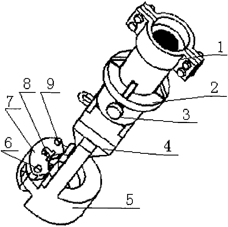
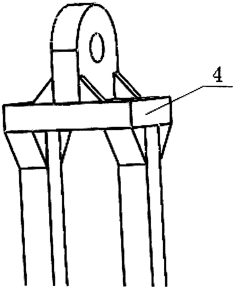
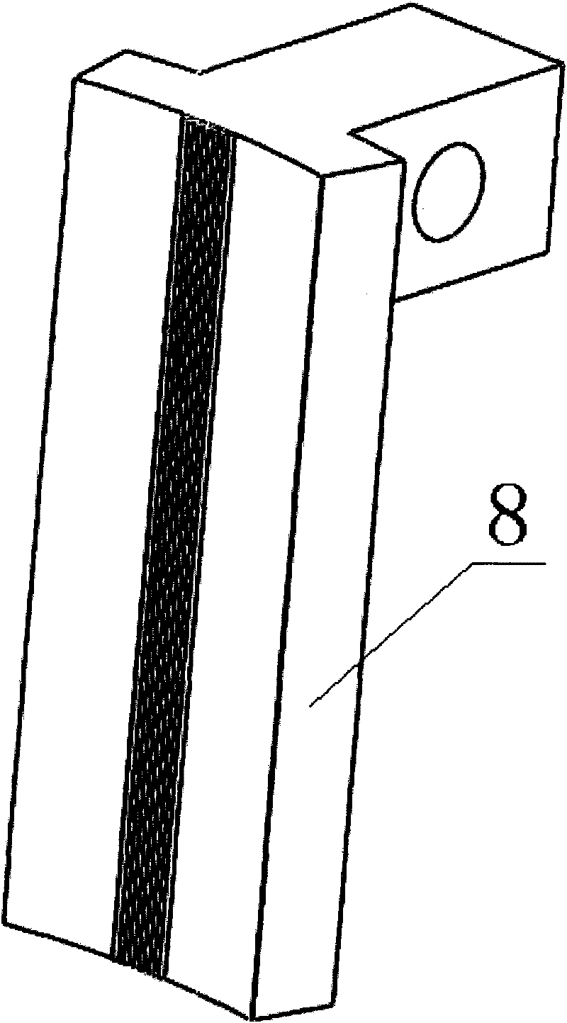
[0024] refer to figure 1 . The torsion-bearing drill pipe elevator device is mainly composed of an upper anti-twist device 1, an upper connecting short 2, a connecting pin 3, a lower connecting short 4, a main clamping block 5, a fixed shaft pin 6, an auxiliary clamping block 7, Lower anti-twist device 8 and safety pin 9 form.

[0025] The upper anti-twist device 1 is a clamping structure with double bolts fixed on the side, that is, the upper anti-twist device 1 is composed of two semi-circular arc-shaped steel plates and two bolts, and the two ends of the semi-circular arc-shaped steel plates are respectively connected with flat steel plates. The thickness of the steel plate is 20mm. The inner walls of the two semicircular steel plates are ...


PUM


Abstract

A torque-withstanding drill pipe elevating device is used for a power swivel to perform drill pipe-tripping operation. In the elevating device of the invention, an upper anti-twist device is a clamping stirrup with sides fixed with bolts, the anti-twist device is fixed on the outside wall of the top of an upper connection pup joint; the lower end of the upper connection pup joint is provided with two lugs, a steel plate which is perpendicular to the two lugs is provided with a pinhole; the upper end of a lower connection pup joint is provided with a single lug, the lower end is provided with two parallel and downward suspension bars, the lower ends of the two suspension bars are welded on the outside wall of the annulated column of a main clamping block; an auxiliary clamping block is locked on the main clamping block through shear pins; and the slip insert of a lower anti-twist device embraces closely a drill pipe coupling to ensure that the drill pipe coupling can rotate with the main clamping block and the auxiliary clamping block. The effects of the invention are as follows: the drill pipe can be firmly clamped during drill pipe-tripping operation; hydraulic dynamic chain tongs are used to complete the screwing operation when the drill pipe and a connection pipe pile are screwed on or screwed off, and the power swivel is used to complete the unscrewing operation between the drill pipe and the connection pipe pile through the drill pipe elevating device, thus increasing the efficiency of the drill pipe-tripping operation.

Description

technical field [0001] The invention relates to the technical field of petroleum and coalbed methane drilling, in particular to a drill pipe elevator, which is a torsion-bearing drill pipe elevator device that can cooperate with a power faucet to realize tripping and tripping of conventional drill pipes. Background technique [0002] The power faucet is inexpensive, small in size, and has some top drive features. The power swivel has a rotating function, and the use of the power swivel to trip the drill pipe has a greater advantage compared with the ordinary rotary table and kelly drilling operation. When the drill pipe is tripped by the power faucet in China, because there is no targeted wellhead tool to cooperate, the traditional operation method is still used for the tripping of the drill pipe, that is, the conventional elevator is used to cooperate with the wellhead tools such as hydraulic tongs to realize the tripping of the drill pipe Operation. The operation of powe...

Claims


Application Information

Patent Timeline
Patent Type & Authority Applications(China)
IPC IPC(8): E21B19/06
Inventor 韩飞纪友哲贾涛朱英杰马汝涛王雪刘洋耿莉
Owner BC P INC CHINA NAT PETROLEUM CORP
Why Eureka
Try Eureka