Air tight construction of changeover valve
An airtight and structural technology, applied to the parts in contact between the valve element and the valve seat, valve details, multi-way valves, etc., can solve the problems of general products without suitable structure and inconvenience, and achieve improved heat resistance, The effect of high airtightness
- Summary
- Abstract
- Description
- Claims
- Application Information
AI Technical Summary
Problems solved by technology
Method used
Image
Examples
Embodiment 1
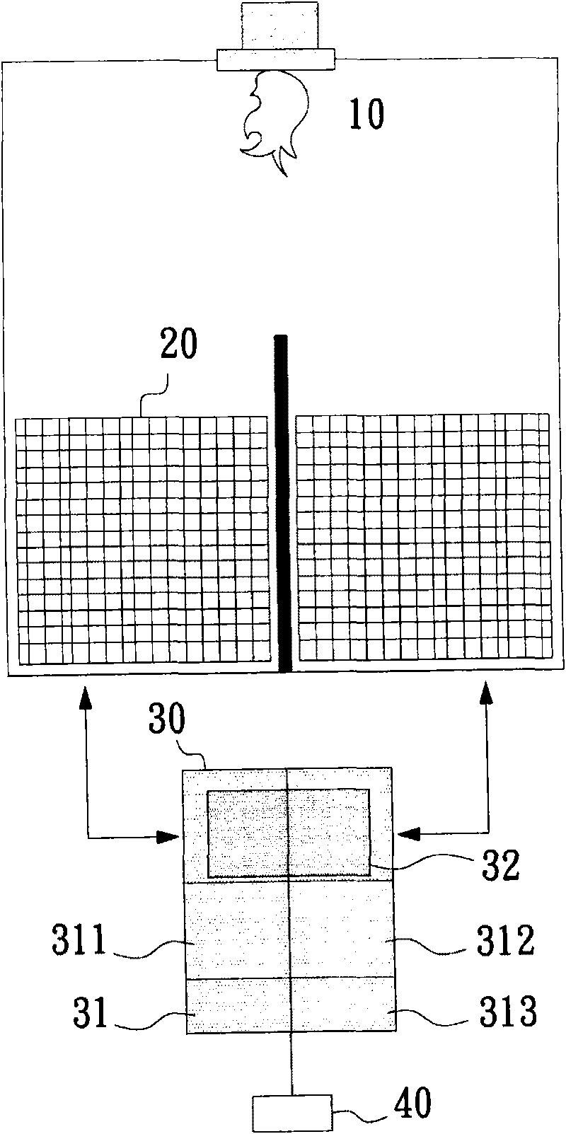
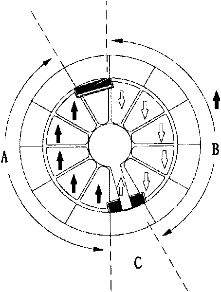
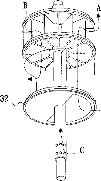
[0059] Figure 4 is a schematic diagram of the first specific embodiment of the airtight structure of the rotary valve of the present invention, Figure 5 yes Figure 4 An enlarged schematic view of the airtight structure in . The airtight structure 50 is arranged between a rotor 32 and a stator 31 in a rotary valve 30 to provide an airtight effect between the rotor 32 and the stator 31 in the rotary valve 30 .
[0060] The airtight structure 50 includes: a first sealing device 60, on which a fixing seat 61 is arranged, and the fixing seat 61 is used to lock the first sealing device 60 on the rotor 32; A connecting part 62, which is to lock the fixed seat 61 on the rotor 32; a first sealing material 63, which is used to make the rotor 32 and the stator 31 contact and seal; a guiding member 64, which is Installed on the fixed seat 61, and guide the first sealing material 63 to contact with the stator 31; a locking member 65, which is used to lock the guide member 64, so that...
Embodiment 2
[0065] Figure 6 It is a schematic diagram of the second specific embodiment of the airtight structure of the rotary valve of the present invention, Figure 7 yes Figure 6 An enlarged schematic view of the airtight structure in . The airtight structure 80 is arranged between a rotor 32 and a stator 31 in a rotary valve 30 to provide an airtight effect between the rotor 32 and the stator 31 in the rotary valve 30 .
[0066] Wherein, the airtight structure 80 includes: a first sealing device 60, and the first sealing device is provided with: a fixing seat 61, and the fixing seat 61 is used to lock the first sealing device 60 on the rotor 32. On; a connecting portion 62, which is to lock the fixed seat 61 on the rotor 32; a first sealing material 63, which is used to make the rotor 32 and the stator 31 contact and seal; a guiding member 64, It is installed on the fixing seat 61, and guides the first sealing material 63 to contact with the stator 31; a locking member 65 is use...
Embodiment 3
[0070] Figure 8 is a schematic diagram of the third specific embodiment of the airtight structure of the rotary valve of the present invention, Figure 9 yes Figure 8 An enlarged schematic view of the airtight structure in . The airtight structure 90 is arranged between a rotor 32 and a stator 31 in a rotary valve 30 to provide an airtight effect between the rotor 32 and the stator 31 in the rotary valve 30 .
[0071] Wherein, the airtight structure 90 includes: a second sealing device 70, the second sealing device 70 is provided with: a fastening member 71, which is to fasten the second sealing device 70 on the rotor 32; The second sealing material 72 is in contact with the stator 31 for sealing.
[0072] Wherein, the second sealing device 70 can be made of rubber, silica gel or Teflon, and the second sealing material 72 can withstand high temperature above 250°C. The cross-section of the second sealing material 72 can be a P-shaped cross-section and can further form an...
PUM
 Abstract
Description
Claims
Application Information
 - R&D
- Intellectual Property
- Life Sciences
- Materials
- Tech Scout
- Unparalleled Data Quality
- Higher Quality Content
- 60% Fewer Hallucinations
Browse by: Latest US Patents, China's latest patents, Technical Efficacy Thesaurus, Application Domain, Technology Topic, Popular Technical Reports.
© 2025 PatSnap. All rights reserved.Legal|Privacy policy|Modern Slavery Act Transparency Statement|Sitemap|About US| Contact US: help@patsnap.com


