
Heat exchanger beneficial to discharge of condensate water

A heat exchanger and condensate technology, applied in heat exchange equipment, evaporators/condensers, refrigerators, etc., can solve problems such as slow airflow, affecting system ventilation and heat transfer, and restricting application fields, and achieve less production equipment. , the effect of saving investment and simple processing technology

Inactive Publication Date: 2010-06-16
JIANGSU KANGTAI HEAT EXCHANGE EQUIP ENG +2
View PDF0 Cites 14 Cited by
  • Summary
  • Abstract
  • Description
  • Claims
  • Application Information

AI Technical Summary

Problems solved by technology

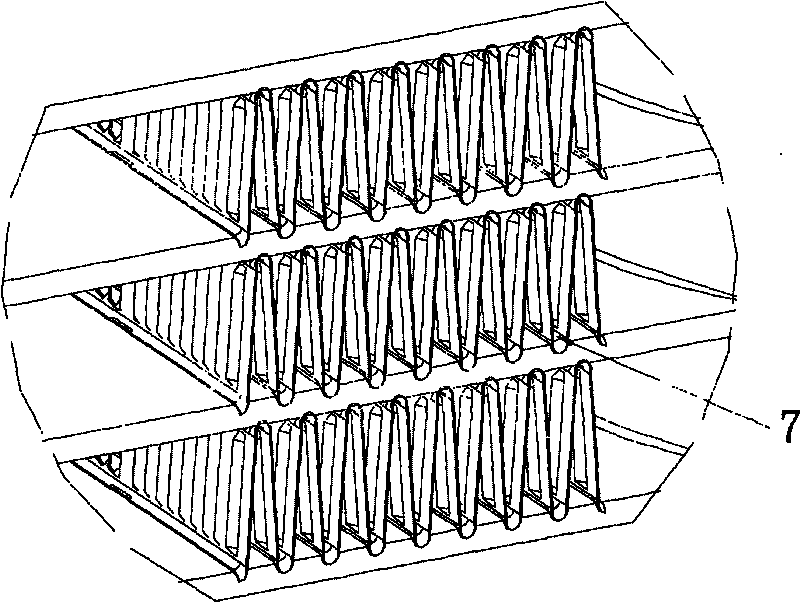
The disadvantage of this structure is that since the heat exchangers of the air-conditioning system are mostly arranged vertically, the small concave arcs at the bottom of the rolled pleated fins ( figure 1 The middle mark 7) is a horizontal straight section. Because the air velocity of household and commercial air conditioners is relatively slow, generally not exceeding 3m / s, in the case of condensed water, the condensed water cannot break free from the effect of surface tension driven by the airflow , and the accumulation of frost and ice in the small concave arc will affect the normal ventilation and heat exchange of the system, and then make the whole system unable to operate normally
Even after the system runs in defrost mode, the condensed water cannot be discharged
[0004] Therefore, the brazed microchannel heat exchanger with the above structure can only be used in the outdoor condenser unit of the cooling-only air conditioner (in heat dissipation mode, no condensed water is produced) because of the above-mentioned obvious defects, and cannot be applied to the evaporator of the cooling-only air conditioner (indoor unit) and heat pump air-conditioning systems, which greatly limit its application fields

Method used


Image

  • Heat exchanger beneficial to discharge of condensate water
  • Heat exchanger beneficial to discharge of condensate water
  • Heat exchanger beneficial to discharge of condensate water

Examples


Embodiment Construction

[0019] The present invention will be further described below in conjunction with the accompanying drawings and specific embodiments.

[0020] figure 1 It is a schematic diagram of the connection structure between rolled pleated fins and flat tubes in the prior art, and is composed of figure 1 In mark 7, it can be seen that the small concave arc at the bottom of the rolled pleated fin is a horizontal straight section. In the case of condensed water, the condensed water gathers in the small concave arc 7 and frosts and freezes, which affects the normal ventilation of the system. heat exchange.

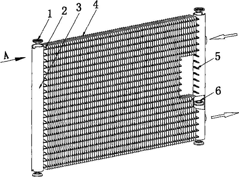
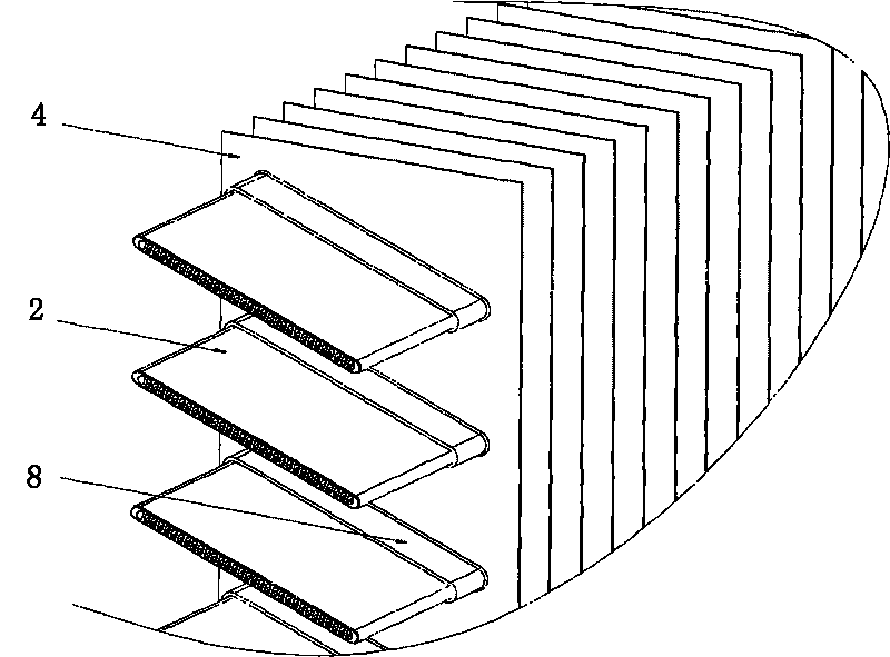
[0021] Depend on figure 2 and image 3 It can be seen that a heat exchanger that facilitates the discharge of condensed water includes a header 3, a blocking cover 1 placed at the end of the header 3, a spacer 6 placed inside the header 3, and the The flat tube 2 connected to the collector 3, and the fins 4 connected to the flat tube 2 are characterized in that: one side of the coll...


PUM


Abstract

The invention relates to a heat exchanger beneficial to discharge of condensate water, comprising a collecting pipe, a flat pipe and a fin. The heat exchanger is characterized in that one side of the collecting pipe and the fin are provided with regularly arrayed flat pipe holes, of which size and shape are matched with the size and shape of the flat pipe section; the flat tube is a flat and straight structure arranged in the transverse direction; the pin is a plain film or a corrugated sheet and is arranged in the longitudinal direction, the flat pipe is arranged in the flat pipe holes of a pin pack. The invention has the beneficial effect that instead of being horizontally arranged, the flat tube is now obliquely arranged, and instead of being staggeringly arranged with fold fin-flat pipe-fin, the fin is now arranged perpendicular to the flat pipe, so that condensate water on a core of the heat exchanger, which is produced by system operation can slide to an oblique fin flanging along the vertically arranged fin and then flow out of the core along the flanging without remaining condensate water. The heat exchanger of the invention can not only be applied to an outdoor unit of a single cold air conditioner but also to an outdoor condenser of an indoor evaporator and a heat pump air conditioner.

Description

technical field [0001] The invention relates to the technical field of heat exchangers, in particular to an all-aluminum brazed micro-channel heat exchanger structure that facilitates the discharge of condensed water. Background technique [0002] The existing all-aluminum brazed micro-channel heat exchanger is a high-efficiency heat exchanger made of all-aluminum material. It transfers heat through multiple sets of flat tubes containing micro-channels and pleated fins with louvers, which significantly improves the heat transfer efficiency. At the same time, it also has obvious advantages such as less consumables, low cost, and strong pressure resistance, and is increasingly widely used in the field of household and commercial air conditioners. But so far, the above-mentioned all-aluminum brazed microchannel heat exchanger can only be applied to the condenser (outdoor unit) of the single-cooling air conditioner, because the condenser is in a heat-dissipating working state a...

Claims


Application Information

Patent Timeline
IPC IPC(8): F25B39/00F28F1/32
Inventor 江秋良刘友明张爱华杨建权
Owner JIANGSU KANGTAI HEAT EXCHANGE EQUIP ENG
Learn More