High-efficiency condenser and air conditioner with same

A condenser and high-efficiency technology, used in evaporators/condensers, refrigerators, refrigeration components, etc., can solve the problem of not fully considering the difference in heat exchange between front and rear rows, imperfect design parameters of double-row heat exchangers, and inability to heat exchangers. Unbalance adjustment and other problems, to achieve the effect of improving heat exchange efficiency, shortening fluorine injection time, and uniform and orderly liquid separation at the inlet

Inactive Publication Date: 2010-06-16
HISENSE (SHANDONG) AIR CONDITIONING CO LTD
View PDF0 Cites 10 Cited by
  • Summary
  • Abstract
  • Description
  • Claims
  • Application Information

AI Technical Summary

Problems solved by technology

The process layout and liquid separator are important aspects of process design, but the existing heat exchangers have the following problems: 1. The existing liquid separator components have large pressure loss and uneven liquid distribution
2. The design parameters of the distance between the front and rear rows of the double-row heat exchanger are not perfect, and the difference in heat transfer between the front and rear rows is not fully considered, so the heat exchanger cannot fully exert its heat transfer capacity
3. There is no capillary tube at the outlet of the subcooling section, and the imbalance of each branch of the heat exchanger cannot be adjusted, so that the overall heat exchange balance of the heat exchanger is insufficient, and the uniformity of heat flux density is poor
4. The inlet pipe group adopts the form of "pipe pipe" or tee, which is prone to uneven distribution
5. The fluorine injection process tube in the condenser is set in the capillary assembly, which is difficult to process, takes a long time to inject fluorine, and has low efficiency

Method used


Image

  • High-efficiency condenser and air conditioner with same
  • High-efficiency condenser and air conditioner with same
  • High-efficiency condenser and air conditioner with same

Examples


Embodiment Construction

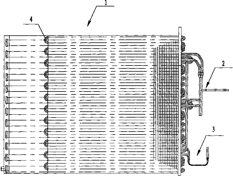
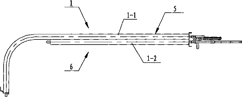
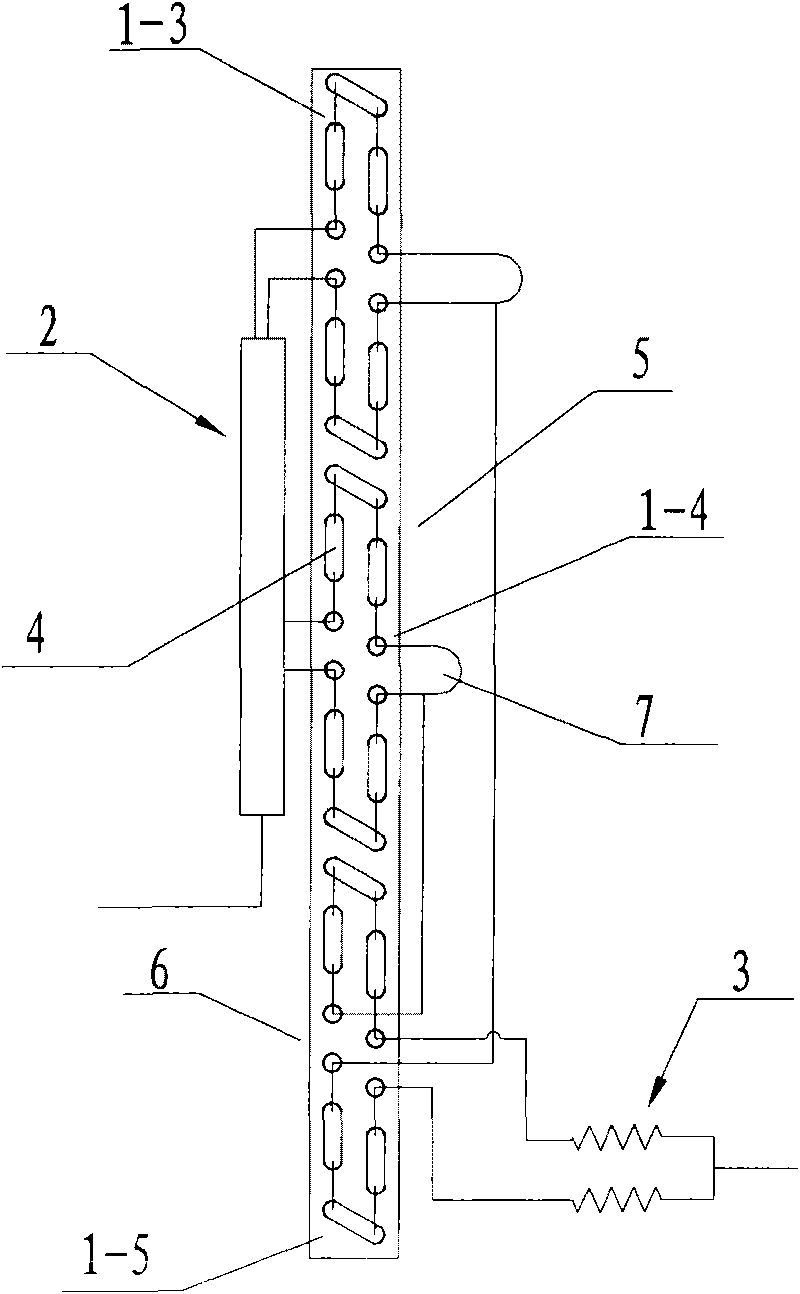
[0038] see figure 1 , figure 2 and image 3 , Condenser 1 is a double row, that is, it is divided into front and rear rows of condensers. The front and rear condensers adopt a long and short row structure, the windward front row condenser 1-1 adopts a long row form, and the leeward rear row condenser 1-2 adopts a short row form. The distance between the end plates of the front row condenser 1-1 is 771mm, that is, the total length is 771mm, the distance between the pieces is 1.4mm, and the number of pieces is 551 pieces; mm, the number of pieces is 362 pieces. The use of long and short row design and appropriate sheet pitch configuration relationship can not only reduce the cost, but also help to improve the overall heat exchange efficiency of the heat exchanger.

[0039] see image 3 , the diversion branches of the superheating section 1-3 and the saturation section 1-4 in the front and rear condensers 1-1 and 1-2 are 4 paths, and the inlet pipe group 2 and the middle li...


PUM


Abstract

The invention provides a high-efficiency condenser and an air conditioner with the same. The high-efficiency condenser can solve the problem that a heat exchanger of the prior art cannot give full play to heat exchange capacity, and adopts the technical scheme that: the high-efficiency condenser comprises a front row condenser, a back row condenser, a U-shaped tube, a fin, an inlet tube stack, an intermediate liquid distributing tube stack and an outlet fluid diversion tube stack, wherein the front row condenser and the back row condenser are provided with a plurality of fluid diversion branches; the front row condenser has a long row; and the back row condenser has a short row. The high-efficiency condenser is characterized in that: the flow paths of the fluid diversion branches are set into a combination of inverted U shapes and regular U shapes. The high-efficiency condenser optimizes the flow path of the condenser, newly designs the inner row heat exchanger, the outer row heat exchanger, the inlet tube stack, the outlet tube stack and the intermediate liquid distributing tube, uniformly distributes refrigerants in each flow path of the heat exchanger, improves the overall heat exchange balance, improves the heat exchange efficiency of the condenser and reduces the manufacturing cost of the condenser.

Description

technical field [0001] The invention belongs to air-conditioning and refrigeration engineering, and in particular relates to a tube-fin type high-efficiency condenser with a new structure. Background technique [0002] Air conditioner heat exchanger process design is very important, whether the design is reasonable or not will directly lead to the level of heat transfer and energy efficiency ratio. The process layout and liquid separator are important aspects of process design, but the existing heat exchangers have the following problems: 1. The existing liquid separator components have large pressure loss and uneven liquid distribution. 2. The design parameters of the distance between the front and rear rows of the double-row heat exchanger are not perfect, and the difference in heat transfer between the front and rear rows is not fully considered, so the heat exchanger cannot fully exert its heat transfer capacity. 3. There is no capillary tube at the outlet of the subcoo...

Claims


Application Information

Patent Timeline
Patent Type & Authority Applications(China)
IPC IPC(8): F25B39/04
Inventor 杜顺祥康月李本卫
Owner HISENSE (SHANDONG) AIR CONDITIONING CO LTD
Why Eureka
Try Eureka