Liquid helium conveying pipeline and heat sink interface form design

A technology for conveying pipelines and liquid helium, which is applied in the field of interface design between liquid helium conveying pipelines and heat sinks, which can solve problems such as system failure, increased consumption of liquid helium, and increased cold loss of pipelines, and facilitate disassembly and assembly , The consumption of liquid helium is reduced, and the effect of solving low temperature cold leakage

Inactive Publication Date: 2010-06-16
BEIHANG UNIV
View PDF0 Cites 11 Cited by
  • Summary
  • Abstract
  • Description
  • Claims
  • Application Information

AI Technical Summary

Problems solved by technology

[0003] The liquid helium external process system can provide liquid helium refrigeration for the heat sink. Since liquid helium is an ultra-low temperature fluid, cold leakage is easy to occur at low temperatures. Causes cold leakage of liquid helium, and the release of the leaked liquid helium into the environment will cause harm to the human body. At the same time, it will also increase the cold loss of the pipeline and increase the consumption of liquid helium. The above problems will eventually lead to the failure of the system to operate normally.

Method used


Image

  • Liquid helium conveying pipeline and heat sink interface form design
  • Liquid helium conveying pipeline and heat sink interface form design

Examples


Embodiment Construction

[0010] The present invention will be further described below in conjunction with the accompanying drawings.

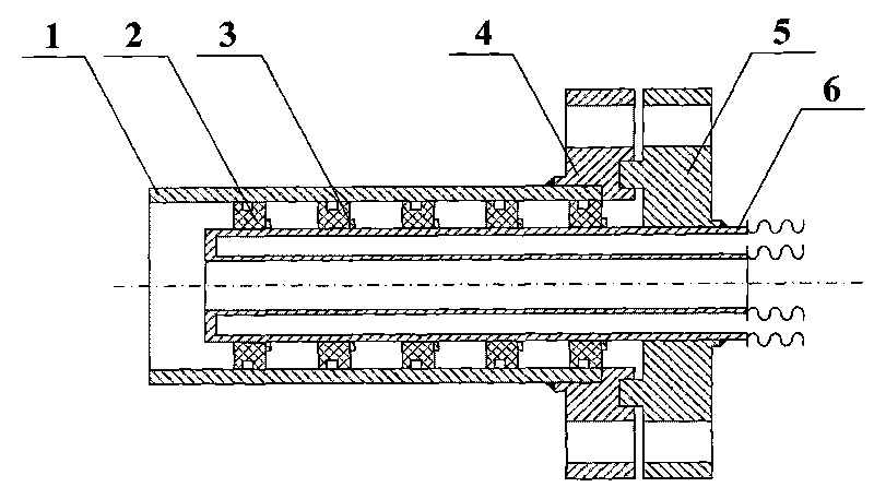
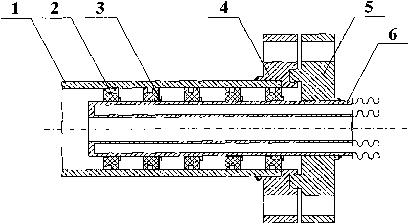
[0011] figure 1 The interface form between the liquid helium delivery pipeline and the heat sink shown is mainly composed of a heat sink pipeline (1), a sealing gasket (2), a positioning ring (3), a container flange (4), a delivery pipeline flange (5), a liquid helium Delivery pipeline (6) is formed.

[0012] Teflon can be used as the sealing gasket material, the number of sealing gaskets is 3 to 10, the connection form of the container flange and the heat sink pipeline is welding, the connection form of the delivery pipeline flange and the liquid helium delivery pipeline is welding, the container flange The flange of the delivery pipeline is connected by bolts, and the liquid helium delivery pipeline adopts a double-layer vacuum Dewar tube with small cold loss.

[0013] The interface between the liquid helium delivery pipe and the heat sink is suitable for both the ...


PUM


Abstract

The invention discloses a liquid helium conveying pipeline and a heat sink interface form, mainly consisting of a heat sink pipeline (1), sealing gaskets (2), a positioning ring (3), a container flange (4), a conveying pipeline flange (5) and a liquid helium conveying pipeline (6). Polytetrafluoroethylene can be used as a material to prepare 3-10 sealing gaskets, the container flange and the heat sink pipeline are connected by welding, the conveying pipeline flange and the liquid helium conveying pipeline are connected by welding, the container flange is connected with the conveying pipeline flange through a bolt, and the liquid helium conveying pipeline adopts a double-layer vacuum Dewar pipe with less cold loss.

Description

【Technical field】 [0001] The invention relates to the form design of the interface between the low-temperature delivery pipeline and the heat sink. The invention is particularly applicable to the design of the interface form between the liquid helium delivery pipeline and the heat sink. 【Background technique】 [0002] An important prerequisite for the study of the plume effect is to ensure the rapid adsorption of the gas in the plume experiment, so that the environmental vacuum can reach the specified index. Most of the high-altitude plume experiments are simulated by nitrogen gas, and the equipment used to absorb the gas in the plume experiment is mainly a cryogenic pump surrounding the inner surface of the vacuum container, that is, a helium plate (liquid helium heat sink). The United States and Germany, which were studied earlier in the world, both adopted this structural form. For example, the STG vacuum plume experimental system of DLR in Germany has a container with ...

Claims


Application Information

Patent Timeline
Patent Type & Authority Applications(China)
IPC IPC(8): F25D23/00F16L23/032F16L59/065
Inventor 蔡国飙凌桂龙王文龙李晓娟黄本诚张国舟
Owner BEIHANG UNIV
Why Eureka
Try Eureka