Laser distance-measuring device and control method thereof

A technology of a distance measuring device and a control method, which is applied in the field of laser distance measuring devices, can solve the problems of inability to calculate to obtain the target object, shrapnel and cam positioning point errors, inability to receive reflected light signals, etc., so as to achieve device volume reduction and manufacturing. The effect of cost reduction and large measurement range

Inactive Publication Date: 2010-06-16
ASIA OPTICAL CO INC
View PDF1 Cites 11 Cited by
  • Summary
  • Abstract
  • Description
  • Claims
  • Application Information

AI Technical Summary

Problems solved by technology

[0002] In today's off-axis system laser ruler, because the internal optical system is designed and configured according to its own measurement range, so due to the limitation of the optical system, the measurement range of the laser ruler must usually be greater than a certain range above 0.3m. The reason is that when the target is at a short distance, such as within 0.3m, the incident angle of the light reflected back due to the light emitted to the target is too large, so that the reflected light guided by the original optical system cannot reach the receiving device, and The reflected light signal cannot be received, and thus the distance of the target cannot be calculated from the reflected light signal
In the current technology, there are also technical means to solve the shortcoming of being unable to measure at close distances. The method of moving the receiving device is used to adjust the position of the receiving device to receive optical signals incident at various angles. The patent document of US Patent No. US005949531A In, a distance measuring device is disclosed. A receiver is installed on one end of the shrapnel, and the other end is fixed on the device body. A cam mechanism is installed under the shrapnel. When the cam mechanism is driven to rotate, due to the contour shape of the cam surface, It will drive the shrapnel to move up and down. Therefore, by controlling the designed surface shape of the cam, the receiver installed at one end of the shrapnel can be controlled to adjust the up and down position by the angle of rotation, so as to control the receiver. position of the receiver to receive light signals incident from various angles, however, using shrapnel and cams to control the position change of the receiver will require a large space to install the shrapnel and cams, and the shrapnel and cams will have material fatigue and wear And cause the shortcomings of positioning point error and so on

Method used


Image

  • Laser distance-measuring device and control method thereof
  • Laser distance-measuring device and control method thereof
  • Laser distance-measuring device and control method thereof

Examples


Embodiment Construction

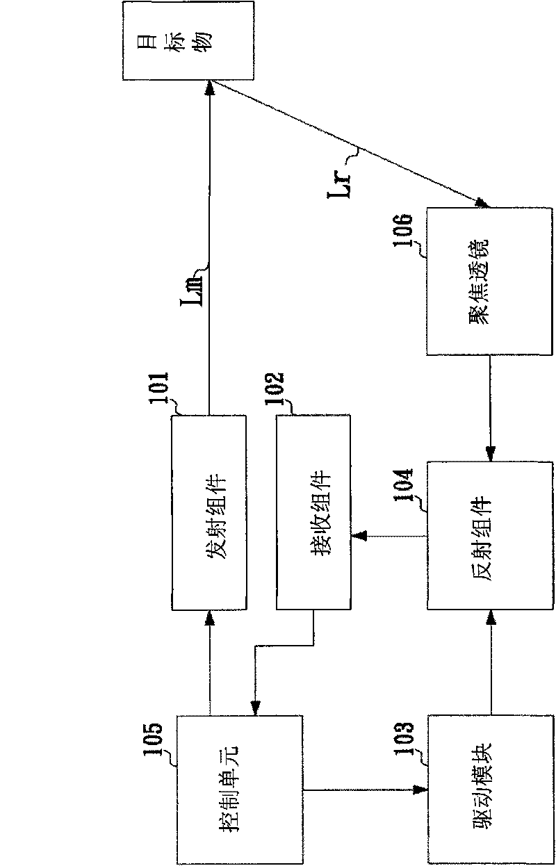
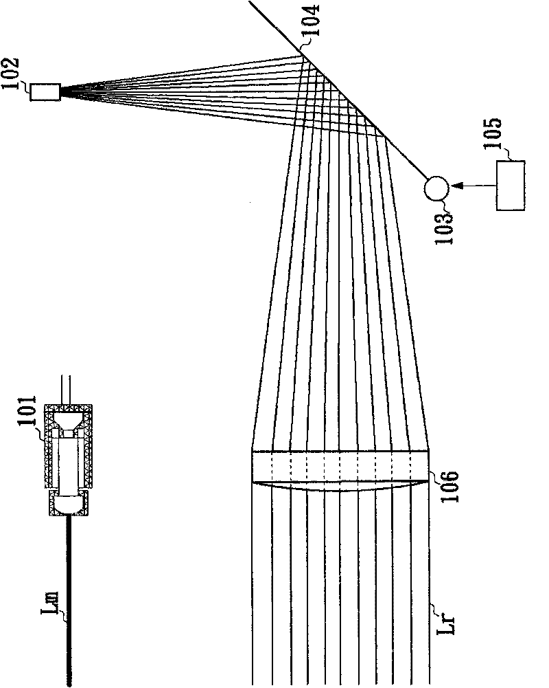
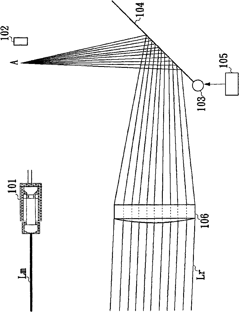
[0014] see figure 1 Shown is the block diagram of the laser ranging device according to the first embodiment of the present invention. The laser ranging device according to the first embodiment of the present invention includes a transmitting component 101 , a focusing lens 106 , a receiving component 102 , a driving module 103 , a reflecting component 104 , and a control unit 105 .

[0015] The emitting component 101 is used for emitting the measurement light Lm to the target object. In this embodiment, the emitting component 101 is a laser module. When the laser distance measuring device intends to measure the distance of the target, the laser module will emit the measurement light Lm to the target. When the measurement light After Lm reaches the target object, it will be reflected back by the target object and become reflected light Lr.

[0016] The focusing lens 106 is used for focusing the reflected light Lr on the receiving component 102 through the reflecting componen...


PUM


Abstract

The invention provides a laser distance-measuring device and a control method thereof, which can measure targets in a far distance and in a close distance. The laser distance-measuring device comprises a transmission assembly, a receiving assembly, a reflection assembly, a focus lens, a drive module and a control unit. The transmission assembly is used for transmitting measuring light to the targets; the receiving assembly is used for receiving reflected light generated from the measuring light reflected by the target; the reflection assembly is used for reflecting the reflected light to the receiving assembly; the focus lens is used for focusing the reflected light to the receiving assembly through the reflection assembly; the drive module is used for adjusting the angle of the reflection assembly through rotation; and the control unit controls whether the drive module rotates or not according to results of comparing intensity sizes of the reflection light received by the receiving assembly with predetermined values.

Description

technical field [0001] The invention relates to a laser distance measuring device, in particular to a laser distance measuring device capable of measuring long and short distances and a control method thereof. Background technique [0002] In today's off-axis system laser ruler, because the internal optical system is designed and configured according to its own measurement range, so due to the limitation of the optical system, the measurement range of the laser ruler must usually be greater than a certain range above 0.3m. The reason is that when the target is at a short distance, such as within 0.3m, the incident angle of the light reflected back due to the light emitted to the target is too large, so that the reflected light guided by the original optical system cannot reach the receiving device, and The reflected light signal cannot be received, and thus the distance of the target cannot be calculated from the reflected light signal. In the current technology, there are ...

Claims


Application Information

Patent Timeline
Patent Type & Authority Applications(China)
IPC IPC(8): G01S7/481G01S17/08
Inventor 蔡宗岳
Owner ASIA OPTICAL CO INC
Why Eureka
Try Eureka