Millimeter wave transceiving system and reflecting plate
A transceiver system, millimeter wave technology, applied in the direction of electromagnetic wave transmission system, transmission system, non-optical transmission system, etc., can solve problems such as difficult ceiling, inability to perform high-precision angle adjustment, heavy mirror weight, etc., and achieve good machinability sexual effect
- Summary
- Abstract
- Description
- Claims
- Application Information
AI Technical Summary
Problems solved by technology
Method used
Image
Examples
Embodiment approach 1
[0083] (Outline of millimeter wave transmission and reception system 100)
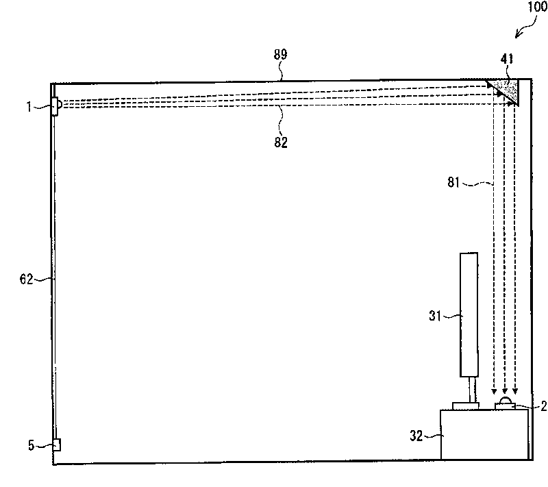
[0084] figure 1 It is an example diagram showing a schematic configuration of the millimeter wave transmission and reception system 100 .
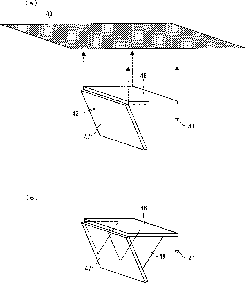
[0085] Such as figure 1 As shown, the millimeter wave transceiver system 100 is set indoors, and includes a transmitting device 1 for transmitting radio waves in the millimeter wave band (hereinafter referred to as "millimeter waves"), and a transmission signal (millimeter wave) for transmitting to the transmitting device 1. ) reflector 41 and the receiving device 2 for receiving the transmission signal (millimeter wave) reflected by the reflector 41 .
[0086] In this embodiment, a millimeter-wave video multiplex transmission system is used as an example for description. The millimeter-wave transceiver system 100 is installed in a living room, etc., for example, and up-converts broadcast waves such as digital broadcasting into signals in the 60 GHz band. This...
Embodiment approach 2
[0191] Below, according to Figure 7 , Figure 8 , Embodiment 2 will be described.
[0192] Figure 7 It is a schematic diagram showing the configuration of the millimeter wave transmission and reception system 200 according to the second embodiment. Figure 8 yes means Figure 7 A side view of the structure of the reflector in .
[0193] Components that are the same as those in Embodiment 1 are also assigned the same component symbols here, and description thereof will be omitted.
[0194] Hereinafter, parts different from Embodiment 1 will be described. In Embodiment 1, reflector 41 (reflector 41a, reflector 41b) with reflective surface 43 was described as flat, but reflector 41c of this embodiment differs from the above in that reflective surface 43c has a concave shape.
[0195] In addition, for example, a tripod 101 is used to fix the transmitter 1 on an appliance 102 such as a cabinet.
[0196] The level adjuster / power supply 5 is arranged on the top of the set 10...
Embodiment approach 3
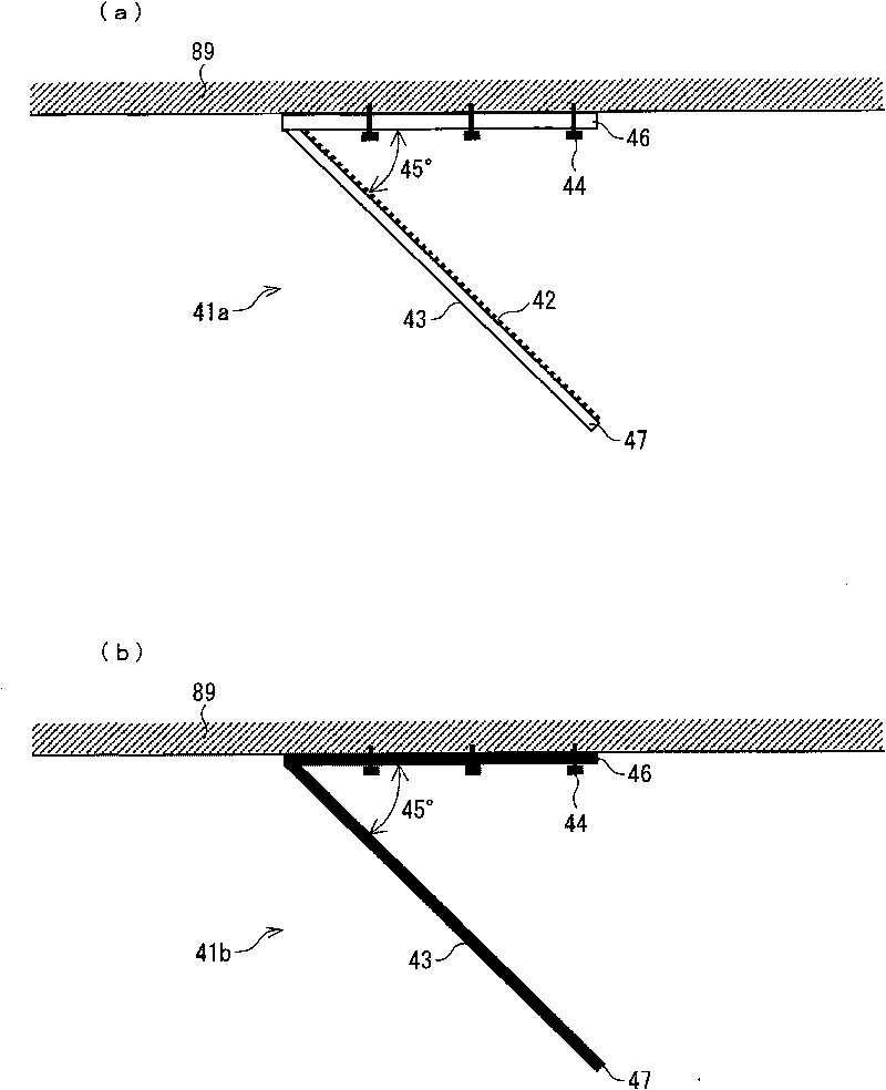
[0201] Below, according to Figure 9 , Figure 10 (a), (b), Figure 11 (a), (b), for the difference in embodiment 3 figure 1 The structure of Embodiment 1 shown will be described.
[0202] Figure 9 It is a schematic diagram showing the configuration of the millimeter wave transmission and reception system 300 according to the third embodiment.
[0203] Figure 10 (a) means Figure 9 A side view of the structure of the reflector, Figure 10 (b) is a side view which shows the modification of the structure of a reflector.
[0204] Components that are the same as those in Embodiments 1 and 2 are also given the same component numbers here, and descriptions thereof are omitted.
[0205] Embodiment 3 differs from Embodiments 1 and 2 in the shape and number of reflecting plates.
[0206] Such as Figure 9 As shown, the level adjuster / power supply 5 is connected to the indoor broadcasting antenna terminal, and the transmitting device 1 is directly connected to the level adj...
PUM
| Property | Measurement | Unit |
|---|---|---|
| Thickness | aaaaa | aaaaa |
| Thickness | aaaaa | aaaaa |
| Thickness | aaaaa | aaaaa |
Abstract
Description
Claims
Application Information
 - R&D Engineer
- R&D Manager
- IP Professional
- Industry Leading Data Capabilities
- Powerful AI technology
- Patent DNA Extraction
Browse by: Latest US Patents, China's latest patents, Technical Efficacy Thesaurus, Application Domain, Technology Topic, Popular Technical Reports.
© 2024 PatSnap. All rights reserved.Legal|Privacy policy|Modern Slavery Act Transparency Statement|Sitemap|About US| Contact US: help@patsnap.com


